Chapter 2: How To Use HVE — Part B
Updated edition, verified against current HVE source code (HVEINV-64, Physics). Original: HVE User's Manual, Seventh Edition (Jan 2006), printed pages 2-40 through 2-69.
Part A: Basic concepts through Event Mode • Part C: Selecting User Options, Getting Help, Video
Contents (Part B)
- Creating Report and Playback Windows
- Creating Case Files
- Creating Databases
- Printing Results
- Setting the View
Creating Report and Playback Windows
Select Playback Mode after creating one or more events. Playback Mode is used to prepare output reports, view trajectory simulations and combine multiple simulation events into a single, coherent sequence. Playback Mode is also used to route these results to your printer or video recording device.
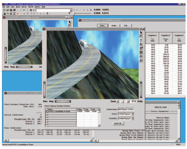 Figure 2-32: The HVE Playback Editor combining the results of multiple simulations into a single coherent sequence.
In Playback Mode, the user creates two types of windows:
- Report Windows
- Playback Windows
Report and Playback Windows are described in the following sections.
Creating Report Windows
Each Report Window contains the results for a single event. To create a Report Window, perform the following steps:
- Select Playback Mode.
- Click on Add New Object. The Report Window dialog will be displayed, containing a list of all the executed events (see Figure 2-33).
NOTE: The Event Status tells you if the selected event has been executed. If the event has not been executed, there will not be reports available.
- Choose an event from the Active Events list.
- If desired, edit the event name.
- Select the desired output report(s).
- Press OK.
(updated: the current Report Window dialog contains the Active Events list, a read-only Status field, an editable Name field, and a multiple-selection Report Type list with Select All and Clear All buttons — so several report windows for one event can be created in a single step.)
The selected output window will be displayed. Output types may be broadly categorized into the following types:
- Numeric Outputs
- Graphic Outputs
- Trajectory Simulations
- Variable Output Table
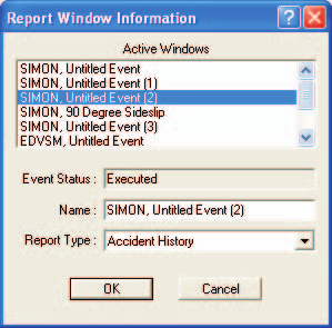 Figure 2-33: The Report Window Information dialog.
Numeric Outputs
Numeric outputs are displayed in Preview Windows (see the Common Reports window reference). The types of numeric outputs are described below.
NOTE: The specific data available in any numeric output window is dependent upon the calculation model.
Accident History — The Accident History output report is a table of positions and velocities for each user-entered path position (see the Accident History reference).
Damage Data — The Damage Data output report normally contains user-entered damage profile data for reconstruction models and calculated damage profile information for simulation models (see the Damage Data reference).
Driver Data — The Driver Data output report normally contains user-entered driver control tables (steering, braking, throttle and gear selection vs time) for simulation models.
Environment Data — The Environment Data output report normally contains the environment parameters used by the reconstruction or simulation model.
Event Data — The Event Data output report normally contains the event set-up data (positions, velocities and event options) used by the reconstruction or simulation model. (updated: the 2006 manual repeated the Damage Data description here by mistake; the Event Data report actually contains event set-up data.)
Human Data — The Human Data output report contains the human anthropometric information supplied by the HVE Human Model and actually used by the reconstruction or simulation model.
NOTE: Although the HVE Human Model contains several hundred parameters, the reconstruction or simulation model may use only a few.
Injury Data — The Injury Data output report contains injury results predicted by an occupant or pedestrian simulator.
Messages — The Messages output report contains information about the run. This information does not normally contain calculated results; rather it contains warnings and diagnostics which describe the run.
Program Data — The Program Data output report normally contains general program input data for documentation purposes. For example, simulation models normally report the simulation control data in this report.
Vehicle Data — The Vehicle Data output report contains the vehicle parameters actually used by the reconstruction or simulation model.
NOTE: Although the HVE Vehicle Model contains several hundred parameters, the reconstruction or simulation model may not use them all.
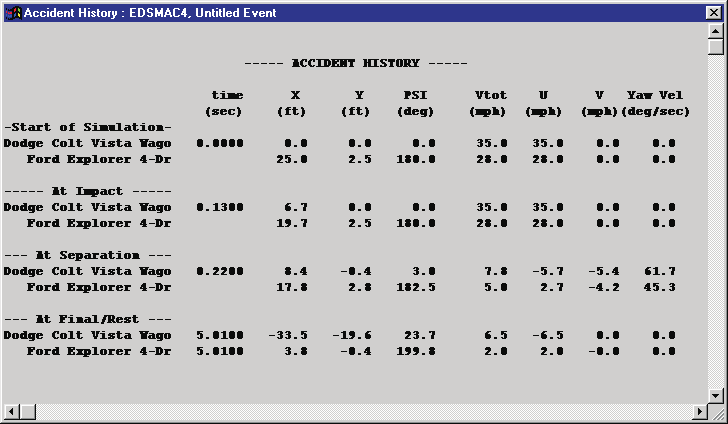 Figure 2-34: A typical Accident History numeric output window.
Graphic Outputs
Graphic output reports are displayed in Report Windows. The types of graphic outputs are described below.
Site Drawing — The Site Drawing output window is a static view of the accident site showing the vehicles at the user-entered positions for each vehicle (e.g., Initial, Impact, Final/Rest). The vehicle speeds at each position are also displayed.
NOTE: The Site Drawing may show the results for one or two vehicles, depending on the number of vehicles in the reconstruction model.
NOTE: The Site Drawing is normally used for reconstruction models.
Damage Profiles — The Damage Profiles output window is a view of the vehicle damage on each vehicle. In addition to the profile itself, the Damage Profile output window may also display the PDOF and other damage-based information.
NOTE: The Damage Profiles window may be either a 2-dimensional or 3-dimensional view, depending on the calculation model.
Momentum Diagram — The Momentum Diagram is a static display which shows a momentum (vector) diagram describing the collision between two vehicles. The Momentum Diagram may be based on vehicle damage data or accident site data.
NOTE: In any case, the Momentum Diagram window requires that sufficient data be entered to establish impact and separation positions and velocities.
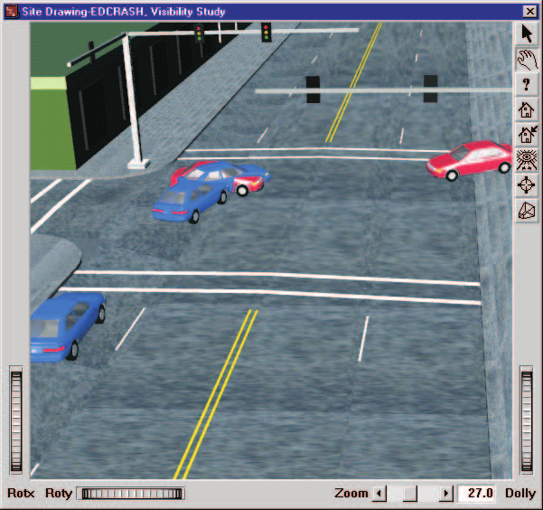 Figure 2-35: A Site Drawing graphic output from EDCRASH.
Variable Output Table
The Variable Output Table is a special output table of simulation results for an individual event, displayed as a function of time. The Variable Output Table can show a tremendous amount of data and is scrollable both horizontally and vertically (see the Variable Output reference ).
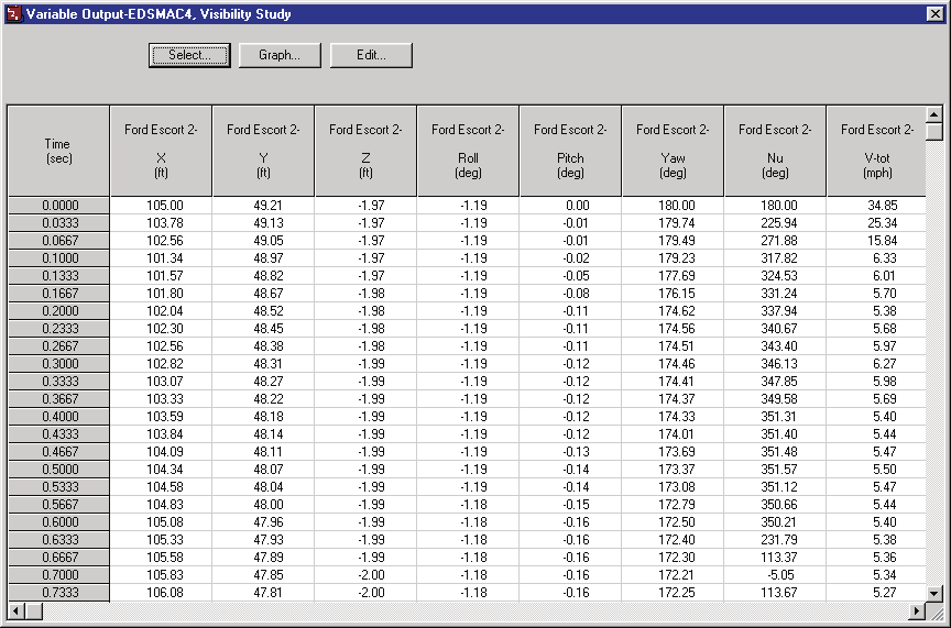 Figure 2-36: The Variable Output Table.
The Variable Output Table includes the following features:
Variable Selection — Choosing Select displays the Variable Selection dialog, allowing the user to choose variables from the available output groups. The selected variables are displayed in the Variable Output Table as a function of time (see the Variable Selection dialog reference).
NOTE: The selectability of variables is determined by the simulation model.
Variable Editing — Each HVE simulation event produces results calculated by the simulation model. Certain non-calculated results may also be assigned by the simulation model; these non-calculated results are editable by the user. For example, a 2-D simulator, which calculates X, Y and Heading, may allow the user to edit the roll, pitch and Z elevation values to produce the appearance of a 3-D simulation. Pressing Edit displays the user-editable table of these non-calculated variables (see the Variable Edit dialog reference).
NOTE: The results made available for editing by HVE are determined by the simulation model.
Graphing — The Graph button allows the user to produce a graph of the first six selected variables in the Variable Output Table (see the Variable Graphing reference).
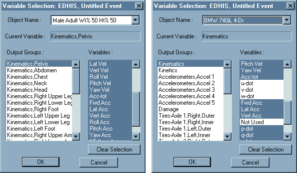 Figure 2-37: The Variable Selection dialogs for humans and vehicles.
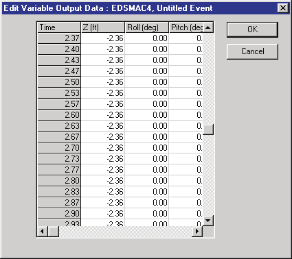 Figure 2-38: The Variable Edit dialog.
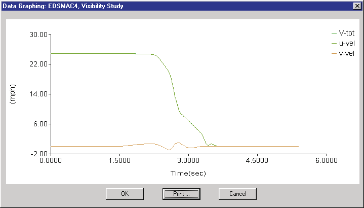 Figure 2-39: The Variable Graphing window.
Trajectory Simulation
The Trajectory Simulation output window is a dynamic visualization of the human and vehicle motion, the same as during Event mode, beginning at the user-entered initial position and continuing until the end of the simulation. Like other output reports, Trajectory Simulations are also displayed in Report Windows (see the Trajectory Report reference).
 Figure 2-40: The Trajectory Simulation window.
The motion in the Trajectory Simulation window is controlled using the Playback Controller, described below.
Creating a Playback Window
The Playback Window allows the user to combine several events (previously set up in Report Windows) to be displayed in a single window. The Playback Window can be used to produce sequences showing multi-vehicle accidents. The Playback Window is also used to produce video output.
To create a Playback Window, perform the following steps:
- Create one or more Trajectory Simulation windows (see previous section).
- Add a Playback Window. (updated: the 2006 manual said to click "Add Playback Window" on the Options menu; in the current version the Playback Window is created from the Playback Editor the same way as other playback objects, and its dialog is titled "Playback Information".) The Playback Window dialog will be displayed, containing a list of all the Report Windows containing Trajectory Simulations (see Figure 2-41).
- Choose one or more Report Windows.
- Enter a name for the Playback Window.
NOTE: Only one Playback Window can be created. (updated: in the current version the Playback Information window is resizable rather than fixed-size.)
The Playback Window initially displays the humans and vehicles for each event at their initial positions. However, because not all action begins at the same time, some editing is usually required. For example, if an impact occurs 3.0 seconds into a sequence, the start of the occupant simulation must be delayed by 3.0 seconds. The editing procedure is described briefly in the following section.
The Playback Window also provides the Video Source and Destination selection, allowing the user to view simulation results, create a compressed movie and also route a simulation movie to a video file:
- Video Source — Option list which allows the user to choose the source of the information displayed in the Playback Window.
- Video Destination — Option list which allows the user to route the Playback Window to a user-selectable destination.
(updated: the current Playback Information window also contains a Video Setup... button, a read-only Recording Information panel showing the current Format (e.g., AVI), Compressor, Recording Size (e.g., HDTV 1080p 1920x1080) and Recording Speed, plus Key Results..., Traffic Signals..., Reorder Events... and Audit Trail... buttons.)
NOTE: For more information about Video Source and Destination, see Video Interface, later in this chapter, and Section Nine, Video Output.
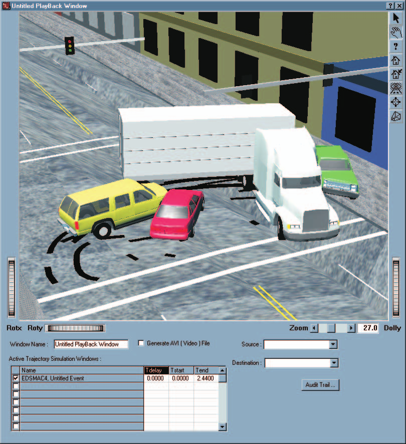 Figure 2-41: The Playback Window dialog.
Playback Controller
The Playback Controller (see Figure 2-42) is used for controlling the motion in Trajectory Simulations and the Playback Window. Like the Event Controller described in Part A, the Playback Controller is much like a VCR in both form and function. It has the same buttons:
- Stop — Stop the simulations displayed in Trajectory Simulation and/or Playback Windows
- Rewind to Start — Return to the start of the simulation
- Reverse — Run the simulation backwards
- Pause — Pause the simulation(s)
- Play — Run the simulation forward
- Advance To End — Advance to the end of the simulation
In addition to the above trajectory simulation control features, the Playback Controller also includes the following components:
- Time Display — Displays the current simulation time
- Frame Control Slider — Allows the user to visually choose a frame within the sequence. To move to the first frame, move the slider all the way to the left; to choose a frame near the middle of the sequence, move the slider to the middle, and so forth. If the user knows the exact frame number, it may be entered directly.
See the Playback Controls reference for the current control layout.
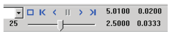 Figure 2-42: The Playback Controller.
Combining and Editing Multiple Events
The timing of multiple trajectory simulation events is affected by the following editing operations, performed using the Active Trajectory Simulations list in the Playback Window (see Figure 2-41):
- Editing Tdelay — Set Tdelay to delay the onset of an event by the user-entered time value
- Editing Tstart and Tend — Set Tstart and Tend to display a portion of the entire event, defined from Tstart to Tend
NOTE: Tstart and Tend allow you to select a specific portion of the event. For example, an occupant simulation may contain 50 milliseconds of irrelevant motion while the human settles into the seat and reaches equilibrium. By selecting Tstart as 50 milliseconds after the output begins, you can remove this undesired motion.
To edit multiple events into the desired time sequence, perform the following steps:
- Open the Playback Window dialog if you have not already done so. It displays a list of active Trajectory Simulation windows for your events.
- Select an event.
- Enter the delay time, start time and end time for the event.
- Repeat the above steps for any number of additional events.
The motion for each event is displayed separately in its Trajectory Simulation Report Window. Use the Report Window to confirm the event(s) are synchronized correctly. The Playback Window shows all the events correctly synchronized in a single window. (updated: the current Playback Information dialog also provides a Reorder Events... button for changing the order in which events are applied.)
Audit Trail
Each Playback Window may contain the results from several events. The merging of these events requires a considerable amount of logic. For example, the pre-impact phase of an accident sequence may use one simulation model, the impact phase may use a second, and one of the vehicles might use a third model for the post-impact phase.
The HVE Playback Window has an internal table to determine which objects are driven by which events during which time intervals. This table is called the Audit Trail; it may be displayed and printed. The Audit Trail is a scrollable text box containing the following information about each event in the Playback Window:
- Report Window Name
- Event Name
- Event Objects used in the Playback Window
NOTE: Even though an event may include two objects, the motion of one of its objects may be controlled by a different event. For example, after impact, a vehicle might roll over. You can use a different (3-D) model to control this portion of the object's motion in the Playback Window.
- The starting and ending times during which the object's motion is controlled by that event
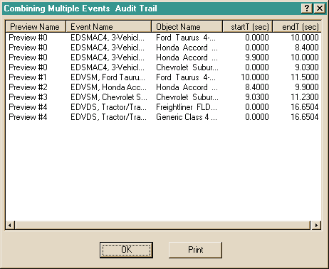 Figure 2-43: The Audit Trail.
The Audit Trail is a convenient way to document the simulation models which control the motion of each object in the Playback Window. To display the Audit Trail for a Playback Window, perform the following steps:
- Choose Audit Trail. The Audit Trail will be displayed, as shown in Figure 2-43.
- After viewing, and possibly printing, the Audit Trail, press OK.
Creating Case Files
HVE creates a file, called the Case file, containing all the active humans and vehicles and the environment. All the events and playback windows are also saved in the case file. At any time, it is possible that many events involving several humans and vehicles have been executed. Therefore, cases can become very large; a 25 MB case file is not uncommon.
Case files are stored in the \case subdirectory of HVE. The directory must
be defined by HVE because these case files are also used to create a virtual
database of humans, vehicles and environments used in previous cases; HVE
needs to know where they are when you first start HVE. See Appendix VIII,
Databases, for more information about the Case Database.
Opening Cases
To open an existing case, choose Open from the File menu (Ctrl+O), as shown in Figure 2-44. If another case is open, HVE will ask the user to save the current case before opening a different one.
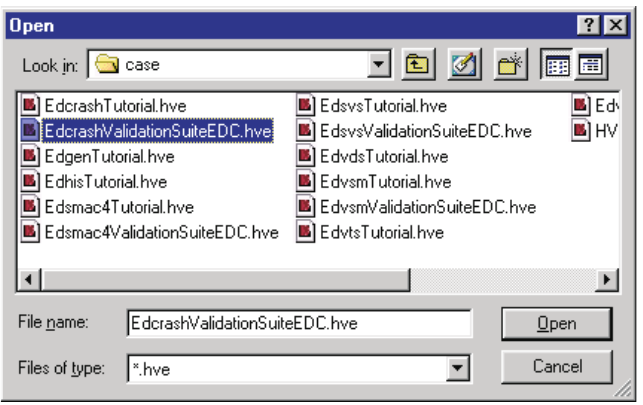 Figure 2-44: The Open Case File Selection dialog.
Saving Cases
To save the current case, choose Save from the File menu (Ctrl+S). HVE will save the case information using the current Case filename.
Save As
If the case hasn't been saved before, HVE will display the Save As file dialog, which requests the user to supply a filename for the case file. The user may also add a case title to the case using the Save As dialog, shown in Figure 2-45. Every case should have a case title, because the title appears in the HVE main menu bar, as well as in the heading on printed output reports.
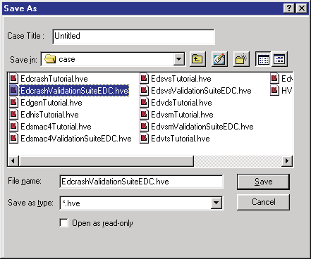 Figure 2-45: The Save Case File Selection dialog.
Starting New Cases
To start a new case, choose New from the File menu (Ctrl+N). If another case file is open, HVE will ask to save the current case before opening a new one. Choosing New completely removes all the case information associated with the current case.
Configuration File
HVE maintains a file, called the configuration file, that keeps track of all the user's current settings and preferences not directly tied to any case. Examples of user preferences include the current status of user options, such as Show Key Results, Units and Autoposition.
Creating Databases
One of HVE's most powerful features is its user-extendible databases for humans, vehicles and tires. By using these databases, the user can truly realize HVE's greatest strength: its object-oriented design. Users will find themselves thinking less about data and more about the interaction of objects (humans, vehicles and environments).
Human Database
The Human database allows the user to select pre-defined humans, according to the following keys:
- Sex
- Age
- Weight Percentile
- Height Percentile
The Human Database is available in the Human Editor's Human Information dialog (see Figure 2-46). By using these keys, HVE creates a human model based on anthropometric studies (the GEBOD databank). This human may then be edited by the user. (updated: the current dialog is titled "GEBOD Human Information"; see the Human Information reference.)
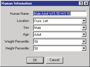 Figure 2-46: The Human Editor's Human Information dialog.
Vehicle Database
The Vehicle Database allows the user to select pre-defined vehicles, according to the following keys:
- Type
- Make
- Model
- Year
- Body Style
The Make, Model, Year and Body Style keys are user-definable (see User Databases, below).
The selectable vehicle types are:
- Passenger Car
- Pickup
- Van
- Sport-Utility
- Truck
- Trailer
- Dolly
- Fixed Barrier
- Movable Barrier
(updated: the 2006 manual listed "SAE Movable Barrier" and "SAE Fixed Barrier"; the current labels are simply "Movable Barrier" and "Fixed Barrier", and an additional "Other" type is available.)
The Vehicle Database is available in the Vehicle Editor's Vehicle Information dialog (see Figure 2-47 and the Vehicle Information reference). After choosing the desired vehicle, HVE loads it into the Vehicle Editor for possible editing and/or use in the current case. (updated: the current version also provides a Vehicle Information search dialog with a Vehicle Search text field for finding vehicles by name.)
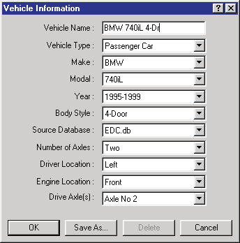 Figure 2-47: The Vehicle Editor's Vehicle Information dialog.
Tire Database
The Tire Database allows the user to select pre-defined tires, according to the following keys:
- Type
- Manufacturer
- Model
- Size
The Manufacturer, Model and Size keys are user-definable (see User Databases, below). The selectable tire types are:
- Passenger Car
- Light Truck
- Heavy Truck
- Mobile Home
(updated: the 2006 manual labeled the third type "Heavy (on-highway) Truck"; the current label is "Heavy Truck".)
The Tire Database is available in the Vehicle Editor's Tire Information dialog (see Figure 2-48 and the Tires and Wheels reference). After choosing the desired tire, HVE assigns it to the current vehicle at the selected wheel location (e.g., Axle 1, Right Side).
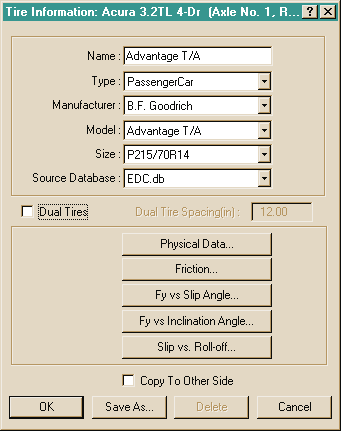 Figure 2-48: The Vehicle Editor's Tire Information dialog.
Generic Databases
HVE includes databases for humans, vehicles and tires. These databases include generic data, that is, data which do not represent any specific human, vehicle or tire, but are representative of typical humans, vehicles and tires for a given size range. The generic databases were produced by the statistical analysis of a large number of humans, vehicles and tires (see references 3.10, 4.9, 4.10, 4.11, 4.26), and contain reasonable estimates for all data necessary to execute any HVE-compatible reconstruction or simulation model. Humans, vehicles and tires created using HVE's generic database may be modified and saved in custom databases, as described below.
Custom Databases
Vehicles and tires may be purchased in custom databases. A custom database differs from a generic database in that it contains actual vehicles (e.g., 1996 Ford Taurus 2-Dr Coupe) and tires (e.g., Goodyear Arriva, P195/75R14). Custom databases are available from EDC, as well as from independent suppliers. Custom databases often include 3-D geometry files for the vehicle body for use in DyMESH simulations, resulting in a life-like appearance. Individual vehicles are also available from EDC.
User Databases
The user may create and save vehicles and tires in his or her own database. These databases are called User Databases. Objects from both generic and custom databases may be saved.
NOTE: The supplier of custom databases may include a license key which prevents unauthorized duplication.
To save the current vehicle in the User Database, perform the following steps:
- Double-click on the current vehicle in the Active Vehicles list. The Vehicle Information dialog will be displayed, showing the database information for the current vehicle.
- Choose Save As. The Save As New Vehicle dialog will appear, displaying the current Vehicle Type, Make, Model, Year and Body Style information. The vehicle's data filename, version number, license key and image filename are also displayed (see Figure 2-49).
- Update these fields by entering the desired data.
- Press OK to save the new vehicle in the User Database.
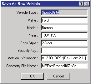 Figure 2-49: The Vehicle Save-As dialog.
NOTE: It is possible to have the same vehicle in two different databases (i.e., EDC and User); however, it is not possible to have the same vehicle twice in the same database. HVE's Database Manager will ask if you want to replace the existing vehicle or enter a different make, model, year or body style.
To save a tire on the current vehicle in the User Database, perform the following steps:
- Click on the desired tire in the Vehicle Viewer. A pop-up menu will be displayed.
- Choose Tire from the pop-up menu. The Tire Information dialog for the selected tire will be displayed.
- Choose Save As. The Save As New Tire dialog will appear, displaying the current Tire Type, Manufacturer, Model and Size information. The tire's data filename, version number and license key are also displayed.
- Update these fields by entering the desired data.
- Choose OK to save the new tire in the User Database.
NOTE: It is possible to have the same tire in two different databases (i.e., EDC and User); however, it is not possible to have the same tire twice in the same database. HVE's Database Manager will ask if you want to replace the existing tire or enter a different manufacturer, model, or size.
A number of issues arise when extending and maintaining databases. Users are encouraged to plan ahead and decide how to approach these issues. For more information about HVE's databases, see Appendix VIII, Databases.
Case Database
Every case includes a number of humans and vehicles. Every time the user
saves a case, these humans and vehicles are saved in the case file. These
humans and vehicles are made available for use in future cases. When
starting HVE, all cases in the \case subdirectory are opened and the
humans, vehicles, environments and tires are extracted to form what is
called the Case Database.
To select humans from previous cases, perform the following steps:
- Select Human mode, then choose Mode > Add... from the main menu. HVE will display a cascade menu containing the options New... and Previous....
- Choose Previous.... HVE displays a dialog listing every case in the
\casesubdirectory and the names of each human included in that case (see Figure 2-50).
NOTE: If the selected case does not include the desired human, select a different case.
- Select the desired human from the list of human names.
- Press Open to add the selected human to the current case.
The selected human will be added to the current case. Use the same procedure to add vehicles from previous cases.
The purpose of the Case Database is not to extend your standard database of humans and vehicles — you should use Save As and create your own User Database for that purpose. Rather, the purpose of the Case Database is to allow you access to unusual vehicles created for, and used in, previous cases. For example, you may remember creating a pickup with a camper. Rather than recreating that vehicle, you can select it directly from the previous case in which it was created and used.
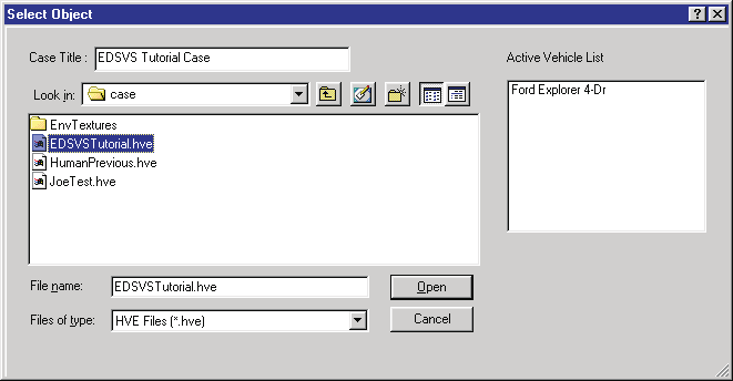 Figure 2-50: The Case Database selection dialog.
Printing Results
HVE allows the user to print several types of output reports, graphs and 3-D views of the accident sequence. The method for printing depends on the object being printed.
Printing Output Windows
In Playback Mode, all output windows may be printed by choosing Print from the File menu. The printable output reports are:
- All Numeric Output Reports (e.g., Accident History, Vehicle Data)
- All Graphic Output Reports (e.g., Damage Profiles)
- Variable Output Table
- Trajectory Simulations (including the Playback Window)
To print an output window, perform the following steps:
- Choose Playback Mode.
NOTE: The output windows are displayed in Playback Mode.
- Choose the desired output report.
- Choose Print... from the File menu (Ctrl+P). The Print dialog is displayed, providing several print options (see Figure 2-51).
- Select from the available print options.
- Press OK. The selected output window is printed on the system printer.
(updated: the current File menu also provides a "Print All..." item for printing all open report windows at once.)
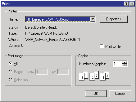 Figure 2-51: The Print dialog.
Printing From Modal Dialogs
If a graph or report is included as part of a modal dialog (i.e., a dialog that requires the user to press OK before continuing), the dialog will contain a Print button.
NOTE: The Print button is required because you cannot select anything (including the Print option in the File menu) until you press OK on the current dialog.
The following modal dialogs have a Print button:
- Several graphs in the Vehicle Editor (e.g., Tire Lateral Force vs Slip Angle)
- The Audit Trail for the current Playback Window
- The Graphing dialog for Variable Output
All printed reports and graphs are printed on the current system printer.
NOTE: The current system printer is installed using the Windows Control Panel.
Printing To a File
The HVE print dialog allows the user to print to file, as well as to the system printer. Printing to file has several important uses:
- Saving the desired information for later printing
- Exporting selected results to a file to be used by another program
To print the current results to file, perform the following steps:
- Using the Print dialog, click Print To File.
- Press OK. The Print to File dialog is displayed (see Figure 2-52).
- Change the current printer name to Generic / Text Only.
NOTE: If a Generic / Text Only printer is not included in the list of printers, you will need to install one using the standard Windows printer installation procedure.
- Enter the desired filename, using
.txtas the extension. - Press OK. The selected report is saved using the specified filename and format.
(updated: the current File menu also provides "Export..." and "FBX Export..." items for exporting data and 3-D geometry directly, which is often more convenient than printing to a file.)
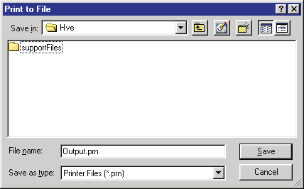 Figure 2-52: The Print To File selection dialog.
Setting the View
The view determines what is visible in any viewer. HVE uses a camera as its viewing paradigm; that is, you choose where you are looking from (the Camera Position), where you are looking at (the Picture Center), and the focal length of the lens. You can also set near and far clipping planes, which determine whether close-up and distant objects are visible.
There are two different ways to set the view:
- Use the thumb wheels on the viewer window borders to set the view interactively, as shown in Figure 2-53.
- Select Set Camera... from the View menu. The Set Camera dialog allows you to directly enter the viewing information described above, as shown in Figure 2-54 (see the Set Camera dialog reference).
Using the thumb wheels has the advantage of allowing the user to quickly and interactively select a view. Using the Set Camera dialog has the advantage of allowing the user to specify the exact camera location and view. The user can also attach the camera to one object and view another object as it moves by. The latter option is useful for visibility studies where the exact viewing position is an issue.
Note that, because HVE's view is 3-dimensional, the term "scale" has no relevance. In a 3-D world, the concept of scale is replaced by the position and focal length of the camera lens used in the view.
Object-based Cameras
By default, the camera is attached to the environment. However, the Set Camera dialog (see Figure 2-54) allows the user to attach the camera to any object (human, vehicle or environment) and attach the view to the same or any other object. This is useful for situations where visibility of drivers or witnesses is an issue.
To set the view using the viewer's thumb wheels, perform the following steps:
- Using the viewer's pick/manipulate icons, choose Pick mode. The cursor will turn into a pointing arrow.
- Click on the Rot X thumb wheel and drag up or down to rotate the entire scene about the viewer's horizontal axis.
- Click on the Rot Y thumb wheel and drag up or down to rotate the entire scene about the viewer's vertical axis.
NOTE: The Rot X and Rot Y thumb wheels rotate the scene about the viewer's axes, not the earth's axes!
- Click the Dolly thumb wheel and drag up to move the camera closer to the scene; drag down to move the camera farther from the scene.
- Using the viewer's pick/manipulate icons, choose Manipulate mode. The cursor will turn into a hand.
- Click in the viewer using the left mouse button and drag the mouse. The scene will rotate about its center.
- Click in the viewer using the middle mouse button and drag the mouse. The scene will translate in the direction of the mouse movement.
NOTE: Setting the view using Manipulate mode takes a little practice. Once you get the hang of it, however, this technique works extremely well!
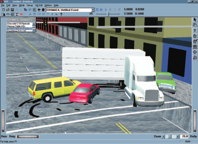 Figure 2-53: HVE viewer thumb wheels.
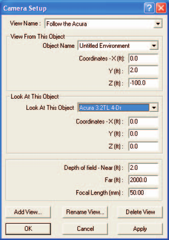 Figure 2-54: The Set Camera dialog.
Overlays
An Overlay is a collection of environment objects which can be made visible or invisible as a group. These objects are usually related in some way. For example, by placing all accident-related artifacts (debris, gouges, skidmarks) on an overlay, the user may turn this overlay off to show the scene's appearance before the accident, and turn it on to show how the scene appeared after the accident. The Overlays dialog, shown in Figure 2-55, is used for displaying and removing selected overlays from the scene (see the Overlays dialog reference).
Overlays are created when the environment is created or edited using the 3-D Editor. Refer to the 3-D Editor section for details on creating and naming overlays.
NOTE: If you use another editor to create your environment, you can still use HVE's 3-D Editor to create overlays.
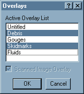 Figure 2-55: The Overlays dialog.
Scanned Image Overlay
A scanned image overlay is a special overlay created from a scanned photograph of the accident scene. The scanned image may be included as part of the environment background using the Environment Information dialog (see the Environment Editor reference).
A scanned background image adds photo-realism to the scene (see Figure 2-56). However, the use of a scanned image requires that the earth-fixed coordinates are known for both the location where the photograph was taken, as well as for the center of the photograph. In addition, the focal length of the camera lens must be known. Finally, to use a scanned image, the view must be fixed; that is, the camera cannot be attached to a moving human or vehicle.
Two excellent uses for scanned background images are:
- To show that a 3-D model of a scene matches the actual scene. This may be accomplished by first showing the scanned image, then showing the 3-D model from the same camera position.
- For a distant sky or background. If a 3-D model of the environment has a relatively flat horizon that fades into the distance, using a photograph of a cloudy sky (which HVE places beneath the 3-D model) creates a realistic environment.
NOTE: The sky remains fixed, even if the camera is attached to a moving human or vehicle. This may reduce the realism.
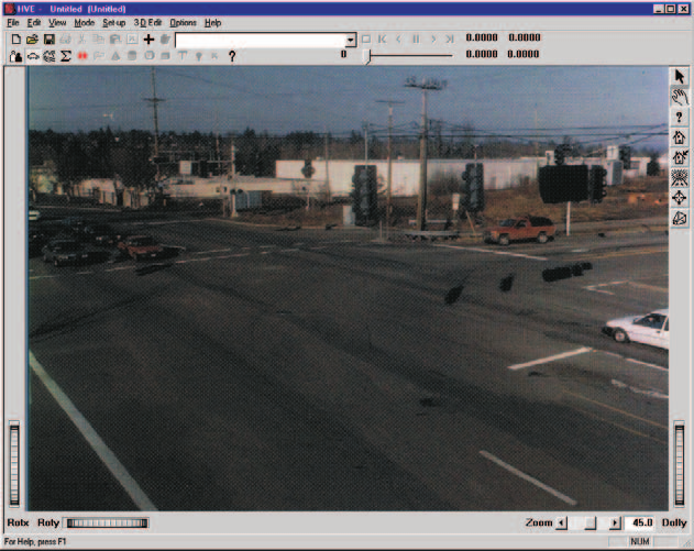 Figure 2-56: A scanned background image.
The individual overlays and scanned background image are displayed or hidden using the Overlays dialog, available in the View menu (see Figure 2-55). The Overlays dialog includes a multiple-selection list box containing the names of every overlay created using the 3-D Editor (the default name is "Untitled"). By default, all overlays are displayed (highlighted). The Overlays dialog also includes a Scanned Image check box to turn the scanned image on and off. To choose the desired overlays and scanned image for display, perform the following steps:
- Choose Overlays... from the View menu. The Overlays dialog will be displayed; all the currently displayed overlays will be highlighted, and the Scanned Image check box will show the current status (on or off) of the scanned image.
- Click on one or more highlighted overlay names to hide them.
- Click on one or more unhighlighted overlay names to show them.
- Click on the Scanned Image check box to show or remove it.
- Press OK.
The selected overlays and scanned background image will be displayed.
Chapter 2 continues in Part C: Selecting User Options, Getting Help, and the Video Interface.
← Previous: Chapter 2 — How To Use HVE | Index | Next: Chapter 2: How To Use HVE — Part C →