Chapter 11 — Vehicle Model Definition (Part E: Drivetrain, Steering and Brake System)
This part covers the vehicle-level systems edited by clicking on the Engine icon (Drivetrain), the Steering Wheel icon (Steering System) and the Brake Pedal/Master Cylinder icon (Brake System) in the Vehicle Viewer.
Drivetrain
The Drivetrain parameters for the current vehicle are displayed and edited using the Drivetrain dialog. The drivetrain is composed of three components that are edited individually:
- Engine
- Transmission
- Differential
Each of these components is described below. See also the code-verified reference page, Drivetrain dialog.
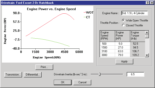 Figure 11-50: The Vehicle Drivetrain dialog, including the Engine, Transmission and Differential.
Engine
The HVE Vehicle engine is modeled by power vs engine speed table data for both a wide-open-throttle (WOT) condition and a closed-throttle (CT) condition.
To display or edit the current vehicle's engine parameters, perform the following steps:
- In the Vehicle Viewer, click on the engine. The Drivetrain dialog will be displayed. The power vs engine speed curve is displayed, showing two curves: one for the WOT condition and the other for the closed-throttle condition.
- To edit the WOT engine parameters, click the WOT Throttle Position radio button. The WOT Power vs Speed Table is displayed. View and/or edit the engine speed and power entries (up to 15 are allowed).
NOTE: Torque is calculated, but not editable.
- To edit the closed-throttle engine parameters, click the Closed Throttle Position radio button. The Closed Throttle Power vs Speed Table is displayed. View and/or edit the engine speed and power entries (up to 15 are allowed).
- Press Apply to update the graphs of power vs engine speed.
- Press Print to print the graph on the system printer.
- Press OK to accept the changes to the current engine properties.
The Engine parameters are described below.
- Engine Name — User-editable description of drivetrain components.
- Throttle Position — Switch between WOT and Closed Throttle positions.
- Engine Speed — Rotational velocity of the crankshaft.
- Engine Power — Rate of work performed by the engine at the current engine speed.
- Engine Torque — Rotational torque produced at the current engine speed (calculated; not editable).
- Drivetrain Inertia — Rotational inertia of drivetrain components.
- Engine Idle Speed (RPM) — (updated: new option, not documented in the legacy manual.) Idle speed of the engine.
- TCS/YSC... — (updated: new option, not documented in the legacy manual.) Displays the Electronic Stability System dialog, used to indicate whether Traction Control (TCS) and/or Yaw Stability Control (YSC) are installed, and to edit their activation thresholds (velocity, yaw velocity error, wheel spin velocity error, wheel side-to-side difference, axle-to-axle difference, drive torque and brake pressure) and activation rates (drive torque change and brake pressure change).
Table 11-26: Engine Parameters
| Parameter | Unit Name | Description |
|---|---|---|
| Engine Name | UtNone | Description of drivetrain components |
| Throttle Position | UtNone | Switch for Wide-Open-Throttle (WOT) and Closed Throttle engine tables |
| Engine Speed | UtEngVelAngular | Engine rotational velocity |
| Engine Power | UtEngPower | Engine power |
| Engine Torque | UtEngTorque | Engine torque (calculated; not editable) |
| Drivetrain Inertia | UtVehInertia | Rotational inertia of drivetrain components |
Transmission
The HVE Vehicle transmission is modeled by a reverse gear, neutral and up to 12 forward gears. The transmission is edited using the Transmission dialog. See also the code-verified reference page, Transmission Data dialog.
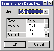 Figure 11-51: The Transmission Data dialog allows the user to edit the transmission ratios.
To display or edit the current vehicle's transmission parameters, perform the following steps:
- In the Vehicle Viewer, click on the Engine icon. The Drivetrain dialog is displayed.
- Click on Transmission. The Transmission dialog is displayed, showing the current number of forward gears and the table of gear ratios.
- If desired, click on the Gears option list to change the number of forward gears.
- View and/or edit the ratios for each gear.
NOTE: A reverse gear is always supplied. A neutral gear, although not displayed, always exists and has no user-editable ratio.
- Press OK to accept the changes to the current transmission. The Drivetrain dialog is still displayed.
- Press OK on the Drivetrain dialog to accept the changes to the drivetrain.
The Transmission parameters are described below.
- Forward Speeds — Number of forward speeds in the current transmission (up to 12).
- Gear Ratios — Ratio for each gear.
- Transmission Type — (updated: new option, not documented in the legacy manual.) Radio buttons selecting Standard (manual) or Automatic. Selecting Automatic enables the Shift Points group, which defines the automatic transmission shift schedule (throttle position vs engine speed, with upshift and downshift lines between the low- and high-speed shift points; the shift schedule graph is redrawn after pressing Apply).
Table 11-27: Transmission Parameters
| Parameter | Unit Name | Description |
|---|---|---|
| Forward Speeds | UtNone | Number of forward speeds in the current transmission |
| Transmission Gear | UtNone | Ratio for each gear |
Differential
The HVE Vehicle differential is modeled by up to 3 ratios. The differential is edited using the Differential dialog. See also the code-verified reference page, Differential Data dialog.
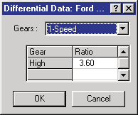 Figure 11-52: The Differential Data dialog allows the user to edit the differential ratios.
To display or edit the current vehicle's differential parameters, perform the following steps:
- In the Vehicle Viewer, click on the Engine icon. The Drivetrain dialog is displayed.
- Click on Differential. The Differential dialog is displayed, showing the current number of gears and the table of gear ratios.
- If desired, click on the Gears option list to change the number of gears.
- View and/or edit the ratios for each gear.
- Press OK to accept the changes to the current differential. The Drivetrain dialog is still displayed.
- Press OK on the Drivetrain dialog to accept the changes to the drivetrain.
The Differential parameters are described below.
- Forward Speeds — Number of speeds in the current differential (up to 3). (The legacy manual said "transmission" here — a typo.)
- Gear Ratios — Ratio for each gear.
- Differential Type — (updated: the current dialog also shows Standard/Limited Slip/Locked radio buttons; these options are presently disabled — the HVE drivetrain model assumes an open (standard) differential, and Limited Slip and Locked are not yet implemented.)
Table 11-28: Differential Parameters
| Parameter | Unit Name | Description |
|---|---|---|
| Forward Speeds | UtNone | Number of forward speeds in the current differential |
| Differential Gear | UtNone | Ratio for each gear |
Steering System Parameters
The Steering System parameters for the current vehicle are displayed and edited using the Steering System dialog. See also the code-verified reference page, Steering System dialog.
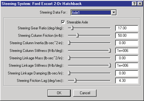 Figure 11-53: The Steering System dialog allows the user to choose which axles are steerable and to assign gear ratio(s) and mechanical properties for the selected steering linkage system.
To display or edit the current vehicle's steerable axles and associated parameters, perform the following steps:
- In the Vehicle Viewer, click on the Steering Wheel icon. The Steering System dialog is displayed.
- Click the Current Axle option list to choose the current axle.
NOTE: The number of available axles is determined by the basic vehicle parameters defined in the Vehicle Information dialog.
- If desired, click the Is Steerable check box to enable editing of the steering system parameters for the selected axle.
- View and/or edit the desired properties.
- Press OK to accept the changes.
The Steering System parameters are described below.
- Axle Selector — Axle number (1, 2 or 3, limited by the number of axles defined in the Vehicle Information dialog).
- Is Steerable Check Box — Switch to allow or disallow steering at the selected axle.
- Gear Ratio — Ratio of the steering wheel angle to the wheel angle.
- Steering Column Friction — Friction torque measured at the steering wheel.
- Steering Column Inertia — Rotational inertia of steering wheel and column.
- Column Stiffness — Torsional stiffness of the steering system between the steering wheel and the wheel on the driver's side.
NOTE: The driver's side is defined in the Vehicle Information dialog.
- Linkage Mass — Mass (weight/g) of all translating linkage components.
- Linkage Stiffness — Torsional stiffness of the steering system between the driver's side wheel and the opposite-side wheel.
- Steering Linkage Damping — Linear damping of the linkage system.
- Steering Friction Lag — Rotational velocity required to develop steering friction torque.
Table 11-29: Steering System Parameters
| Parameter | Unit Name | Description |
|---|---|---|
| Axle Selector | n/a | Current axle number |
| Is Steerable | boolean (TRUE or FALSE) | Check box; if TRUE, the current axle is steerable |
| Gear Ratio | UtVehSteeringRatio | Ratio of the steering wheel angle to the wheel angle |
| Steering Column Friction | UtSteTorque | Frictional torque in steering column |
| Steering Column Inertia | UtVehInertia | Rotational inertia of steering wheel and column |
| Column Stiffness | UtVehSteeringStiffness | Torsional stiffness of the steering system between the steering wheel and the wheel on the driver's side |
| Linkage Mass | UtVehMass | Total mass of all translating linkage components |
| Linkage Stiffness | UtVehSteeringStiffness | Torsional stiffness of the steering system between the driver's side wheel and the opposite-side wheel |
| Steering Linkage Damping | UtVehDamp | Linear damping of linkage |
| Steering Friction Lag | UtVehVelAngular | Friction null band for full column friction |
Brake System Parameters
The Brake System parameters for the current vehicle are displayed and edited using the Brake System dialog (Brake System Pressure vs Pedal Force). See also the code-verified reference page, Brake System Pressure vs Pedal Force dialog.
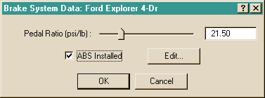 Figure 11-54: The Brake System dialog allows the user to assign the master cylinder pedal ratio (master cylinder pressure per unit of brake pedal force application) and ABS System status.
To display or edit the current vehicle's brake master cylinder pressure ratio, perform the following steps:
- In the Vehicle Viewer, click on the Brake Pedal/Master Cylinder icon. The Brake System dialog is displayed.
- View and/or edit the master cylinder pressure ratio.
- If desired, click on the ABS Installed checkbox to activate the vehicle's antilock brake system.
- If desired, press Edit to display and edit the vehicle's current ABS System parameters.
- Press OK to accept the changes.
The Brake System parameters are described below.
- Pedal Ratio — Ratio of master cylinder pressure per unit of brake pedal force.
NOTE: While using the Event Editor, Driver Controls, the user may assign a table of pedal force vs time. The entered pedal force is multiplied by the master cylinder pedal ratio to determine the current brake system pressure.
NOTE: For airbrake systems, the Pedal Ratio is normally set equal to 1.0; thus, for an airbrake system, the pedal force is also equal to the treadle valve outlet pressure.
- Brake System Type — (updated: new option, not documented in the legacy manual.) Radio buttons selecting the type of brake system installed on the vehicle: Hydraulic or Air.
- Brake Type on Each Axle — (updated: new group, not documented in the legacy manual.) Displays and edits the brake assembly type (Disc or Drum) installed on each axle. This setting is also updated automatically when a specific brake design is chosen in the Brake Assembly dialog (Disc and Air Disc designs set it to Disc; drum-based designs set it to Drum). A warning message is issued when the dialog opens if the right and left brake types on an axle are different, as this is probably a mistake.
- ABS Installed Checkbox — Assigns ABS System parameters. Also enables the Edit pushbutton that displays the ABS System Data dialog and allows editing of the ABS System variables (updated: system-level ABS parameters — control source, ABS algorithm, control method, cycle rate, ABS pressure threshold, ABS velocity threshold, low friction threshold, and delay parameters: delay method, apply delay and release delay).
NOTE: Clicking this checkbox also enables the ABS Designer option and the antilock options in the Wheel Brake Assembly dialog (see Part D, Figure 11-36).
Table 11-30: Brake System Parameters
| Parameter | Unit Name | Description |
|---|---|---|
| Pedal Ratio | UtBraPedalRatio | Brake system pressure per unit of pedal force |
| ABS Installed | UtNone | Flag indicating an ABS system is installed on the vehicle |
HVE Brake Designer
The HVE Brake Designer provides a detailed brake design capability integrated directly within the HVE simulation environment. This feature allows vehicle designers and safety researchers to develop a specific brake design for each wheel and evaluate the resulting vehicle performance using a predefined suite of maneuvers or compliance test simulations. The HVE Brake Designer also includes a detailed tool for simulating ABS.
The Brake Designer is accessed from the Brake Assembly dialog (via the Brake Type option list and Edit Brake pushbutton — see Part D) and from the ABS Designer pushbutton (per-wheel ABS data) and the Brake System dialog's ABS Edit pushbutton (system-level ABS data). The individual Brake Designer dialogs are documented in the code-verified reference pages in Brakes and Powertrain: Disc Brake, Duo-Servo, Duplex, Single Piston, Dual Piston, Dual Wedge and Brake Material Properties. (updated: the legacy manual described the Brake Designer in detail in its Section Eleven; the current brake types additionally include Air Disc.)
Source: HVE User's Manual (Version 5, Seventh Edition, Jan 2006), Chapter 11, pages 11-87..11-98 — updated against source code (HVEINV-64, Physics) 2026-07-05.
← Previous: Chapter 11 — Vehicle Model Definition (Part D: Brakes, Tires and Wheels) | Index