Chapter 11 — Vehicle Model Definition (Part C: Suspension)
Suspension Properties
The suspension parameters of the vehicle are displayed and edited using the Suspension Data dialog (updated: the legacy manual calls this the "Suspension Information" dialog; the current dialog is titled "Suspension Data" and identifies the current vehicle, axle number and side, e.g., "Suspension Data: ... (Axle No. 1, Left Side)").
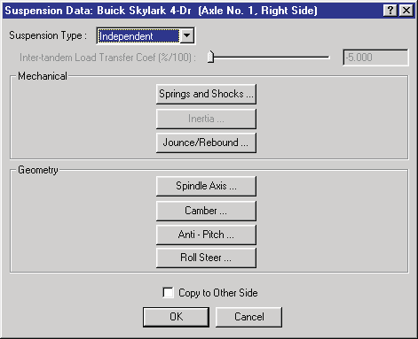 Figure 11-22: The Suspension Data dialog allows the user to choose specific suspension properties for viewing and editing.
The Suspension Data dialog includes pushbuttons allowing the user to select specific suspension properties:
- Suspension Type
- Roll Couple Distribution (updated: added since the legacy manual — see below)
- Inter-tandem Load Transfer (Tandem Axle suspension types only)
- Mechanical Properties (Springs and Shocks, Inertias, Jounce/Rebound Stops)
- Geometry Properties (Spindle Axis, Camber and Half-track Tables, Anti-pitch and Roll Steer)
Each of these properties is described in the following sections. See also the code-verified reference page, Suspension Data dialog.
Suspension Type
The HVE Vehicle Model includes the following suspension types:
- Independent — The right and left wheels move independently from each other (see Figure 11-23a).
- Solid Axle — The right and left wheels are rigidly connected (see Figure 11-23b).
- Tandem, 4-Spring — A set of two solid axle suspensions sharing an articulated spring support, such that the force on the rear of the leading spring is transferred to the front of the trailing spring (see Figure 11-23c).
- Tandem, Walking Beam — A set of two solid axle suspensions connected by a rigid link (see Figure 11-23d).
(updated: the tandem types are offered in the list only where a tandem axle set is possible — on rear axles of vehicles with more than two axles, and on trailers or dollies with more than one axle. Otherwise the list contains only Independent and Solid Axle.)
To choose the suspension type for any axle, perform the following steps:
- Click the right or left wheel for the selected axle. The Suspension Data dialog for the selected wheel is displayed.
- Click on the Suspension Type option button to display the Suspension Type option list, and select one of the available types.
NOTE: Inertial properties are disabled for independent suspensions.
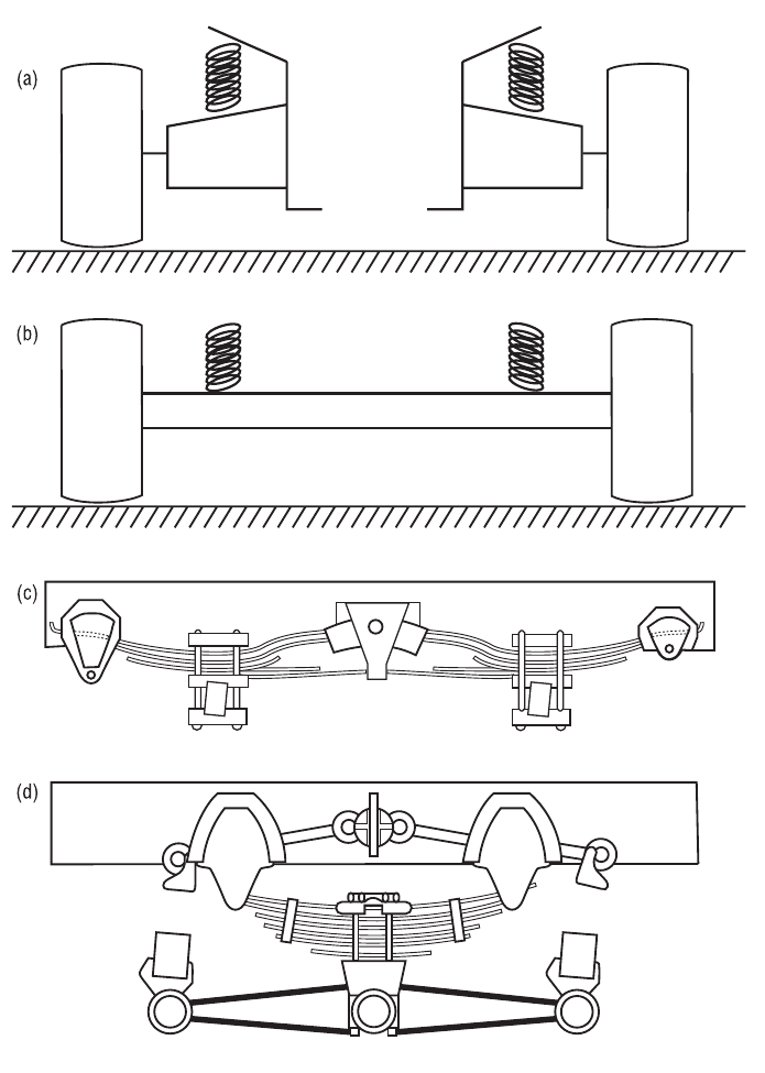 Figure 11-23: Suspension Types: Independent (a), Solid Axle (b), Tandem Axle, 4-Spring (c) and Tandem Axle, Walking Beam (d).
Roll Couple Distribution
(updated: this option was added after the legacy manual was written.) A slider/edit field for the fraction (%/100) of the total sprung mass roll couple (lateral load transfer) reacted at the selected axle. Values at the individual axles are automatically balanced so that the distribution over all axles totals 1.0 — for example, changing the value at a rear axle adjusts the front axle share accordingly; on three-axle vehicles the remainder is split between the other axles. The controls are disabled if the vehicle has fewer than two axles, or if the vehicle has no driver location defined (except movable barriers).
Inter-tandem Load Transfer
If the selected suspension type is a tandem axle (either 4-Spring or Walking Beam), the Inter-tandem Load Transfer parameter is enabled, allowing the user to enter a value (%/100) for the inter-tandem load transfer for the selected axle set. To enter the inter-tandem load transfer for a tandem axle suspension, perform the following steps:
- Click on Suspension Type and choose a tandem axle suspension type (4-Spring or Walking Beam). The inter-tandem load transfer parameter is enabled.
- Enter the desired value.
Springs and Shocks
The Springs and Shocks properties for the selected wheel location are displayed and edited using the Springs and Shocks dialog. See also the code-verified reference page, Springs and Shocks dialog.
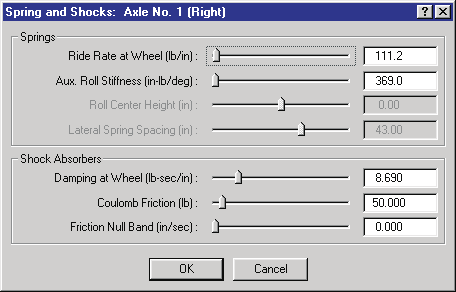 Figure 11-24: Springs and Shocks dialog for selected wheel location.
To display or edit the spring and shock parameters for the selected wheel position, perform the following steps:
- In the Vehicle Viewer, click on the desired wheel. The Unsprung Mass options for the selected wheel are displayed.
- Choose Suspension from the Unsprung Mass option list. The Suspension Data dialog is displayed.
- Choose Springs and Shocks. The Springs and Shocks dialog is displayed.
- View and/or edit the desired properties.
- Press OK to accept the changes. The Suspension Data dialog is still displayed.
- If desired, click Copy To Other Side to make the changes apply to both sides.
- Press OK to accept the suspension changes to the selected wheel position(s).
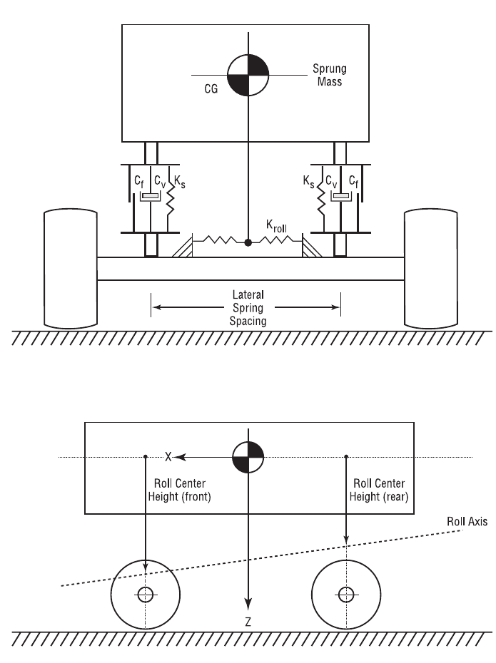 Figure 11-25: Suspension parameters used in the HVE Vehicle Model. Ks, Cv and Cf are spring rate, damping rate and coulomb friction, respectively, for each wheel position. Kroll is the additional roll stiffness contribution due to an anti-sway bar.
The Springs and Shocks properties are described below.
- Ride Rate at Wheel — Spring rate (force per unit of wheel travel) at the selected wheel due to the spring.
- Auxiliary Roll Stiffness — Roll stiffness (torque per unit of sprung mass roll) added by the addition of an anti-sway bar.
- Roll Center Height — Vertical distance from the sprung mass CG down (+) to the suspension roll center.
- Lateral Spring Spacing — Lateral distance between springs for solid axle suspension types.
- Damping Rate at Wheel — Velocity-dependent suspension force due to shock absorbers.
- Coulomb Friction — Friction force required to initiate suspension travel.
- Friction Null Band — Minimum suspension velocity required for full coulomb friction force.
Table 11-12: Suspension Spring and Shock Parameters
| Parameter | Unit Name | Description |
|---|---|---|
| Ride Rate | UtSusForce | Linear force vs deflection characteristic effective at the wheel |
| Auxiliary Roll Stiffness | UtSusRollStiff | Moment per unit of body roll produced by an anti-sway bar |
| Roll Center Height | UtSusDispLength | Height of the roll axis measured at the suspension |
| Lateral Spring Spacing | UtSusDispLength | Lateral distance between left and right springs for solid axle suspensions |
| Damping at Wheel | UtSusDamp | Damping rate effective at the wheel |
| Coulomb Friction | UtSusForce | Force required to initiate suspension travel |
| Friction Null Band | UtSusVelLinear | Suspension velocity required for full coulomb friction |
Axle Inertia
The Suspension Inertial properties for the selected wheel location are displayed and edited using the Axle Inertia dialog.
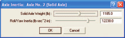 Figure 11-26: Suspension Inertia dialog for selected axle — the selected wheel shares these parameters with the wheel on the other side of the vehicle.
To display or edit the suspension inertial parameters for the selected wheel/axle, perform the following steps:
- In the Vehicle Viewer, click on the desired wheel. The Unsprung Mass options for the selected wheel are displayed.
- Choose Suspension from the Unsprung Mass option list. The Suspension Data dialog is displayed.
- Choose Axle Inertias. The Axle Inertia dialog is displayed.
NOTE: The Axle Inertia option is only available for solid axle suspension systems.
- View and/or edit the desired properties.
- Press OK to accept the changes. The Suspension Data dialog is still displayed.
- If desired, click Copy To Other Side to make the changes apply to both sides.
NOTE: This action is actually irrelevant for the inertias dialog because it automatically applies to the axle shared by both wheels.
- Click OK to accept the suspension changes to the selected wheel position(s).
The Suspension Inertial properties are described below.
- Weight — Total weight of the axle and springs.
NOTE: The Vehicle Editor actually divides your entered value by the current gravitational constant (see Environment Editor) and stores the resultant mass. That way, if you take the vehicle to the moon, it will behave correctly!
NOTE: The weight of the wheels and brakes should not be included here! By convention, the weight of each wheel assembly, including the brake, is to be included in the tire weight (see Tire Physical Parameters).
- Roll/Yaw Inertia — Roll and yaw inertia of the axle. Per the above note, do not include wheel inertias; they are included with the tires.
NOTE: The pitch inertia of the axle is assumed to be negligible.
Table 11-13: Suspension Inertial Parameters
| Parameter | Unit Name | Description |
|---|---|---|
| Weight | UtSusForce | Weight of the suspension, excluding wheels and brakes |
| Roll/Yaw Inertia | UtSusInertia | Roll and yaw rotational inertias of axle, excluding wheels and brakes |
Jounce/Rebound
The Jounce and Rebound properties for the selected wheel location are displayed and edited using the Jounce/Rebound dialog. Suspension stops are used to limit the travel of the suspension. See also the code-verified reference page, Jounce and Rebound dialog.
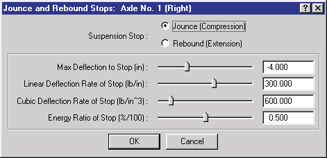 Figure 11-27: Jounce and Rebound dialog for selected wheel.
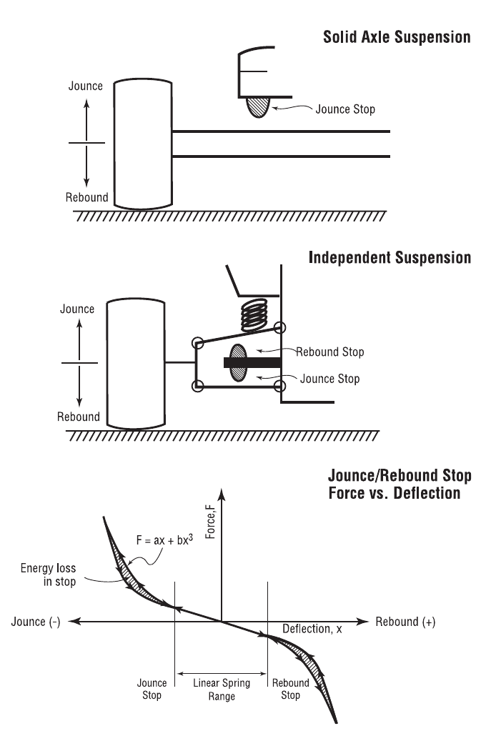 Figure 11-28: Suspension Jounce and Rebound parameters.
To display or edit the suspension stop parameters for the selected wheel, perform the following steps:
- In the Vehicle Viewer, click on the desired wheel. The Unsprung Mass options for the selected wheel are displayed.
- Choose Suspension from the Unsprung Mass option list. The Suspension Data dialog is displayed.
- Choose Jounce/Rebound. The Jounce/Rebound dialog is displayed.
- Click the Jounce radio button to view and/or edit the desired jounce stop properties.
- Click the Rebound button to view and/or edit the desired rebound stop properties.
- Press OK to accept the changes. The Suspension Data dialog is still displayed.
- If desired, click Copy To Other Side to make the changes apply to both sides.
- Click OK to accept the suspension changes to the selected wheel position(s).
The Jounce/Rebound properties are described below.
- Jounce/Rebound Button — Type of stop: Jounce (compression travel limit) or Rebound (extension travel limit).
- Maximum Deflection to Stop — Suspension travel distance from equilibrium to selected stop.
- Stop Linear Rate — Linear constant (force per unit of wheel travel) of the selected suspension stop.
- Stop Cubic Rate — Cubic constant (force per unit of wheel travel) of the selected suspension stop.
- Stop Energy Ratio — Ratio of conserved to total energy (restitution) of the selected suspension stop.
Table 11-14: Suspension Jounce/Rebound Parameters
| Parameter | Unit Name | Description |
|---|---|---|
| Stop Type | n/a | Location of stop (Jounce or Rebound) |
| Maximum Deflection | UtSusDispLength | Suspension travel from equilibrium to jounce or rebound stop |
| Linear Stop Rate | UtSusRateLinear | Spring linear constant (force per unit of wheel travel) of the selected suspension stop (the legacy table said "cubic" here — a typo) |
| Cubic Stop Rate | UtSusRateCubic | Spring cubic constant (force per unit of wheel travel) of the selected suspension stop |
| Energy Ratio | UtSusPercent | Ratio of conserved to total energy (restitution) of the selected suspension stop |
Spindle Axis
The Spindle Axis geometry properties for the selected wheel location are displayed and edited using the Spindle Axis dialog. See also the code-verified reference page, Spindle Axis dialog.
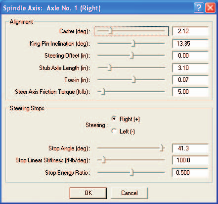 Figure 11-29: Spindle Axis dialog for selected wheel.
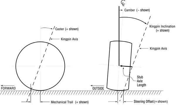 Figure 11-30: Suspension Spindle Axis geometry parameters.
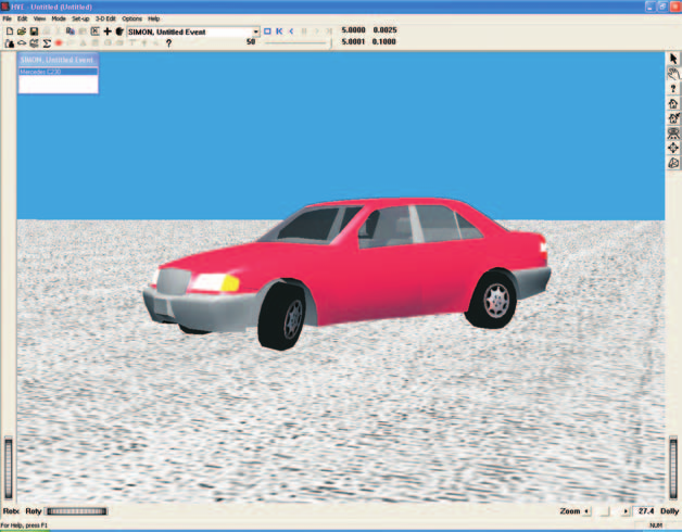 Figure 11-31: Effect of suspension alignment (in particular, caster, kingpin inclination and stub axle length) on the geometry of a steered wheel — note left front wheel.
Alignment
The Alignment parameters, especially Caster, Camber, Kingpin Inclination and Steering Offset (see Figure 11-30), play an important role in determining how tire forces on a steerable axle affect directional response.
NOTE: Some simulation models assume the wheel steers about a vertical axis through the tire plane. This is a simplification. A wheel on a steerable axle actually steers about the kingpin axis. Some simulation models (e.g., SIMON) rigorously model this behavior.
To display or edit the Alignment parameters for the selected wheel position, perform the following steps:
- In the Vehicle Viewer, click on the desired wheel. The Unsprung Mass options for the selected wheel are displayed.
- Choose Suspension from the Unsprung Mass option list. The Suspension Data dialog is displayed.
- Choose Spindle Axis. The Spindle Axis dialog is displayed.
- View and/or edit the desired Alignment properties.
NOTE: Kingpin Inclination, Steering Offset and Stub Axle Length are inter-related. Editing the Kingpin Inclination or Stub Axle Length will automatically recalculate Steering Offset. Similarly, editing Steering Offset will automatically update Stub Axle Length.
Steering Stops
The Steering Stop parameters define the logical limit to steer angles (+ or −) at each wheel. They are also used by the Steer DOF model, when it is employed, to calculate the steering torque that results when a wheel is steered beyond its limit.
To display or edit the Steering Stop parameters for the selected wheel position, continue as follows:
- Click on the Steering radio button and choose the Right or Left steering stop.
- Edit the Stop Angle, Stiffness and/or Stop Energy Ratio as desired.
- Press OK to accept the changes to the Alignment and Steering Stop parameters. The Suspension Data dialog is still displayed.
- If desired, click Copy To Other Side to make the changes apply to both sides of the vehicle.
- Click OK to accept the suspension changes to the selected wheel position(s).
NOTE: The Spindle Axis dialog is displayed only for steerable axles! (See Steering System.)
The Spindle Axis Alignment properties are described below.
- Caster — The fore-aft angle of the spindle axis (see Figure 11-30). This angle is largely responsible for the self-aligning properties of a steerable axle.
NOTE: Caster Angle is defined according to SAE J670e as positive (+) when the top of the axis tilts rearward (see Figure 11-30).
- Kingpin Inclination — The angle in front elevation between the steering axis and a line parallel to the vehicle-fixed z axis (see Figure 11-30). This angle, along with the caster angle, is responsible for the self-aligning properties of a steerable axle.
NOTE: Kingpin Inclination Angle is defined according to SAE J670e as positive (+) when the top of the axis tilts inward, regardless of right or left side (see Figure 11-30).
- Steering Offset (Scrub Radius) — The distance from the center of the tire contact patch to the point where the steering axis intersects the ground at equilibrium conditions. This distance produces a steering torque (positive or negative, depending on the sign of the scrub radius) due to longitudinal tire force (either braking or driving).
NOTE: This value should be kept small. Otherwise, unwanted steering effects will be introduced on acceleration or braking.
- Stub Axle Length — (Also called Kingpin Offset at Wheel Center.) The distance from the steering axis to the center of the wheel (see Figure 11-30). As described above, Kingpin Inclination, Steering Offset and Stub Axle Length are inter-related; changes to one of these parameters affect the others.
- Toe-in — The difference in distance between the center of the tire plane at the spindle and the front of the tire.
- Steer Axis Friction Torque — The coulomb friction in the steering axis. This friction produces torque that resists steering moments, either from the tire-terrain interface or from the steering wheel. This parameter affects the Steer DOF model.
The Steer Axis Steering Stop parameters are described below.
- Steering Stop — This radio button allows the user to select the desired stop (Right Steer or Left Steer).
- Stop Angle — The vehicle-fixed steering angle at which the stop is reached.
- Stop Stiffness — The mechanical stiffness of the steering stop. Additional steering will be resisted by a torque that attempts to return the wheel towards zero steer.
- Stop Energy Ratio — The ratio of conserved to total energy of the selected steering stop (this property is analogous to Jounce and Rebound Stops; see Figure 11-28). This parameter keeps the wheel from bouncing off the steering stop.
Table 11-15: Spindle Axis Parameters
| Parameter | Unit Name | Description |
|---|---|---|
| Caster | UtSusDispAngle | Fore-aft angle of spindle axis |
| Kingpin Inclination | UtSusDispAngle | Lateral angle of spindle axis |
| Steering Offset (Scrub Radius) | UtSusDispLength | Lateral distance from the steering axis to the center of the tire contact patch, measured at the road plane |
| Stub Axle Length | UtSusDispLength | Distance from the steering axis to the center of the wheel |
| Toe-in | UtSusDispLength | Difference in the lateral distance between the tire centerline, measured at the front and rear of the tire |
| Steering Stop | n/a | Stop selector for right or left steering stop |
| Stop Angle | UtSusDispAngle | Steering angle at which the stop is reached |
| Stop Linear Stiffness | UtVehSteeringStiffness | Mechanical stiffness of the steering stop |
| Stop Energy Ratio | UtNone | Ratio of conserved to total energy in the steering stop |
Camber & Half-track Table
The Camber and Half-track properties for the selected wheel location are displayed and edited using the Camber & Half-track Table dialog. See also the code-verified reference page, Camber dialog.
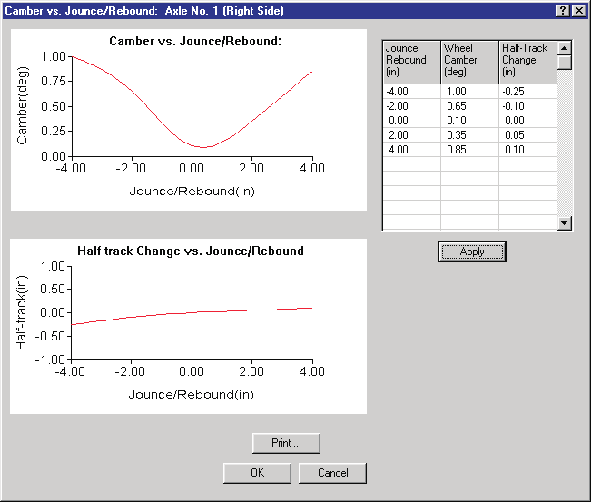 Figure 11-32: Camber and Half-track Table dialog for selected wheel.
To display or edit the camber and half-track tables for the selected wheel position, perform the following steps:
- In the Vehicle Viewer, click on the desired wheel. The Unsprung Mass options for the selected wheel are displayed.
- Choose Suspension from the Unsprung Mass option list. The Suspension Data dialog is displayed.
- Choose Camber & Half-track Table. The Camber & Half-track Table dialog is displayed.
- View and/or edit the desired properties.
- Press Apply to graph the changes to the camber and half-track tables.
- Press Print to print the tables.
NOTE: The tables are printed on the system printer. See Printing for more information.
- Press OK to accept the changes. The Suspension Data dialog is still displayed.
- If desired, click Copy To Other Side to make the changes apply to both sides.
- Press OK to accept the suspension changes to the selected wheel position(s).
The Camber and Half-track Table properties are described below.
- Jounce/Rebound — Suspension travel from equilibrium (see Figure 11-28). Jounce (compression) is negative; rebound (extension) is positive.
- Camber — Camber angle (see Figure 11-30) at the specified suspension deflection.
NOTE: Camber angle is defined according to SAE J670e as positive (+) when the top of the wheel tilts outward, regardless of right or left side (see Figure 11-30).
- Half-track Change — Change in lateral wheel position due to suspension jounce or rebound.
Table 11-16: Camber and Half-track Table Parameters
| Parameter | Unit Name | Description |
|---|---|---|
| Jounce/Rebound | UtVehDispLength | Suspension travel from equilibrium to Jounce (−) or Rebound (+) stop |
| Camber | UtVehDispAngle | Camber angle of wheel at specified suspension deflection |
| Half-track Change | UtVehDispLength | Change in lateral wheel position due to suspension jounce or rebound |
Anti-Pitch
The Anti-Pitch properties for the selected wheel location are displayed and edited using the Anti-Pitch dialog. See also the code-verified reference page, Anti-Pitch dialog.
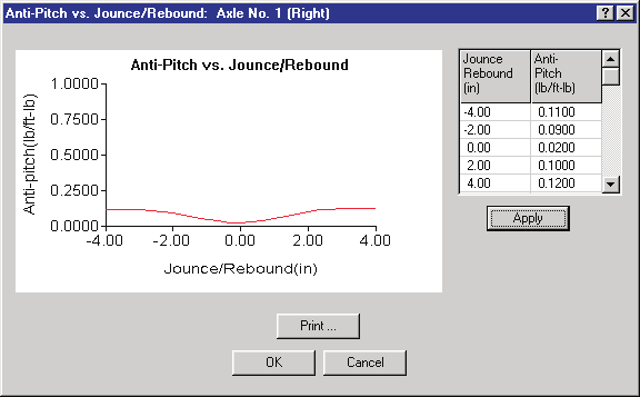 Figure 11-33: The Vehicle Anti-Pitch dialog allows the user to enter suspension anti-pitch characteristics.
To display or edit the anti-pitch table for the selected wheel position, perform the following steps:
- In the Vehicle Viewer, click on the desired wheel. The Unsprung Mass options for the selected wheel are displayed.
- Choose Suspension from the Unsprung Mass option list. The Suspension Data dialog is displayed.
- Choose Anti-pitch. The Anti-pitch Table dialog is displayed.
- Enter jounce/rebound and a corresponding anti-pitch value. Up to 15 pairs of data may be entered.
- Press OK to accept the changes. The Suspension Data dialog is still displayed.
- If desired, click Copy To Other Side to make the changes apply to both sides.
- Click OK to accept the suspension changes to the selected wheel position(s).
The Anti-pitch Table properties are described below.
- Jounce/Rebound — Suspension travel from equilibrium (see Figure 11-28). Jounce (compression) is negative; rebound (extension) is positive.
- Anti-pitch — Anti-pitch force at the specified suspension deflection.
Table 11-17: Anti-pitch Table Parameters
| Parameter | Unit Name | Description |
|---|---|---|
| Jounce/Rebound | UtSusDispLength | Suspension travel from equilibrium to Jounce (−) or Rebound (+) stop |
| Anti-pitch | UtSusAntiPitch | Anti-pitch force at given suspension jounce or rebound |
Roll Steer
The Roll Steer properties for the selected wheel location are displayed and edited using the Roll Steer dialog. The roll steer dialogs are different for independent and solid axle suspensions: independent suspensions use the polynomial-coefficient dialog with a Roll Steer vs. Jounce/Rebound graph; solid axle (and tandem) suspensions use a single-coefficient dialog. See also the code-verified reference pages, Roll Steer dialog (independent) and Roll Steer Properties (solid/tandem axle).
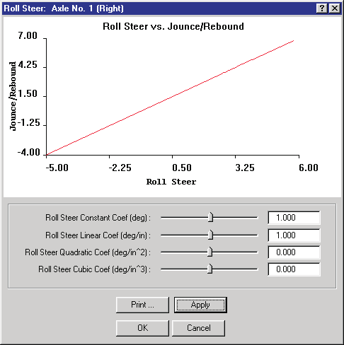 Figure 11-34: Roll Steer dialog for independent suspensions.
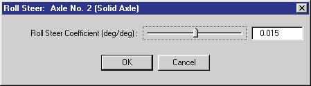 Figure 11-35: Roll Steer dialog for solid axle suspensions.
To display or edit the roll steer parameters, perform the following steps:
- In the Vehicle Viewer, click on the desired wheel. The Unsprung Mass options for the selected wheel are displayed.
- Choose Suspension from the Unsprung Mass option list. The Suspension Data dialog is displayed.
- Choose Roll Steer. The Roll Steer dialog is displayed.
- View and/or edit the desired properties.
- Choose Apply to graph the changes.
- If desired, choose Print to print a graph (independent types).
- Press OK to accept the changes. The Suspension Data dialog is still displayed.
- If desired, click Copy To Other Side to make the changes apply to both sides.
- Press OK to accept the suspension changes to the selected wheel position(s).
The Roll Steer parameters are described below.
- Jounce/Rebound — Suspension travel from equilibrium (see Figure 11-28). Jounce (compression) is negative; rebound (extension) is positive.
- Roll Steer Coefficients — For independent suspensions, the constant, linear, quadratic and cubic coefficients of the wheel steer angle vs jounce/rebound polynomial. For solid axle suspensions, a single roll steer coefficient: the ratio of wheel (axle) steer to body roll. (The legacy manual repeated the Anti-pitch description here — a typo.)
Table 11-18: Roll Steer Parameters
| Parameter | Unit Name | Description |
|---|---|---|
| Jounce/Rebound | UtSusDispLength | Suspension travel from equilibrium to Jounce (−) or Rebound (+) stop |
| Constant | UtSusDispAngle | Initial steer angle at zero roll |
| Linear Coef | UtSusLinearRollSteer | Linear roll steer vs jounce/rebound |
| Quadratic Coef | UtSusQuadRollSteer | Quadratic roll steer vs jounce/rebound |
| Cubic Coef | UtSusCubicRollSteer | Cubic roll steer vs jounce/rebound |
| Coefficient (Solid) | UtNone | Ratio of wheel steer to body roll |
Source: HVE User's Manual (Version 5, Seventh Edition, Jan 2006), Chapter 11, pages 11-40..11-61 — updated against source code (HVEINV-64, Physics) 2026-07-05.
← Previous: Chapter 11 — Vehicle Model Definition (Part B: Exterior) | Index | Next: Chapter 11 — Vehicle Model Definition (Part D: Brakes, Tires and Wheels) →