Chapter 12 — Creating & Editing Environments
The HVE Environment Editor is used for creating and editing environments for the current HVE case. These environments may also be used in other cases. This chapter describes how to create and edit environments, beginning with a description of the Environment Editor's components.
NOTE: The environment is optional; none is required. If an environment is not supplied, the surface is assumed to be flat and cannot be visualized.
NOTE: Refer to the next chapter, Environment Model Definition, for a detailed description of each Environment Model parameter.
Environment Editor Components
To use the Environment Editor, choose Environment Mode using the mode selector. This puts HVE in Environment Mode and allows access to the Environment Editor's components:
- Environment Information Dialog — The Environment Information dialog is used for adding an environment to the current case and for editing its parameters.
- Environment Viewer — The Environment Viewer is used for visualizing the current environment.
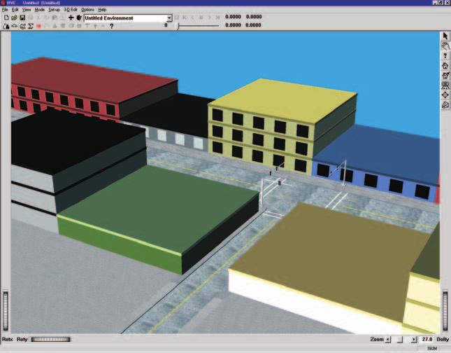 Figure 12-1: Environment Editor dialog and Viewer, showing the Blind Intersection environment model used in the EDSMAC4 Tutorial.
Environment Editor Dialog
The Environment Editor dialog is the heart of the HVE Environment Editor. The dialog includes the following functionality:
- Add Environment — Allows the user to add an environment to the current case and displays two options: New and Previous. Choose New to create a new environment; choose Previous to add an environment from a previous HVE case. These options are further described below.
- Current Environment Label — Displays the name of the current environment. Click on the Object Info button on the toolbar to display the Environment Information dialog for the current environment.
NOTE: The Current Environment Label serves exactly the same purpose as the Active Humans List or Active Vehicles List.
- 3-D Editor — Loads the current environment into the 3-D Editor for editing of its physical and visual properties. To launch the 3-D Editor, select Launch 3D Editor from the 3D-Edit menu option.
Environment Viewer
The Environment Viewer displays the current environment. It contains the following components:
- Current Environment — Allows the user to visualize the current environment.
NOTE: There are no pickable objects in the Environment Viewer.
- Viewer Controls — Allows the user to Rotate, Pan, Zoom and set the current Pick Mode (see Chapter 2 for details about using the viewer controls).
Adding a New Environment
A new environment is added to the current case using the Environment Editor dialog. To add a new environment, perform the following steps:
-
Click on Add New Object. The Environment Information dialog (see Figure 12-2) will be displayed. (updated: this dialog is a tabbed property sheet. Three top-level fields — Name (Environment Name), Date and Time — sit above the tabs, and the tabs organize the remaining parameters: Terrain, Sky, Physical, Location and Traffic Signals. In HVE-3D all five tabs are shown; in HVE-2D only the Terrain tab is present. See the code-verified Environment Information Dialog.) The following user-definable parameters are available:
-
Location Database (Location tab) — A user-editable database of locations:
- City, State/Province and Country — A user-entered location name. No formatting is required; however, the user is encouraged to maintain a consistent format to improve the usability of the database.
- Latitude and Longitude — Used to define the global latitude and longitude, entered in degrees.minutes.seconds. N and S denote north and south latitudes, respectively; E and W denote east and west longitudes, respectively.
- GMT — (Also called UTC offset.) The difference between the local standard time and the time at zero longitude. West longitudes are negative (e.g., New York City is -5 hours).
NOTE: The location is used, along with the time and date of the crash and the orientation of the earth-fixed coordinate system (see below), to determine the location of the sun in the environment. See Chapter 13, Environment Model Definition.
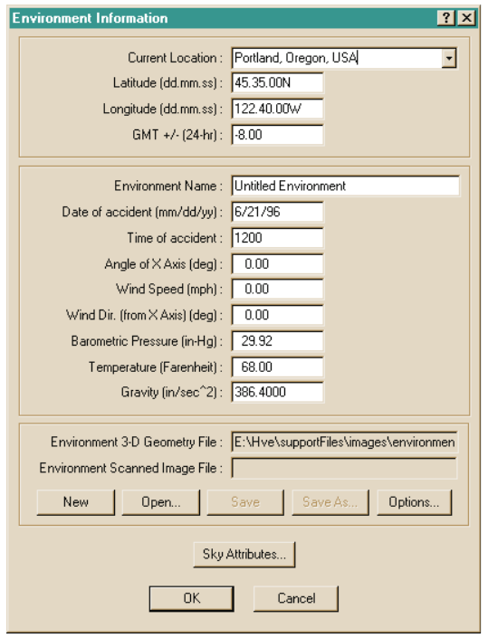 Figure 12-2: Environment Information dialog. See the code-verified field reference: Environment Information Dialog.
- Name (top-level field) — A user-editable field allowing the user to assign a name to the current environment.
- Date (top-level field) — The date of the crash or test being simulated. (updated: the entry format follows the user's date-style preference — mm/dd/yyyy (US) or dd/mm/yyyy (European) — and the field label displays the expected format.)
- Time (top-level field) — The standard time of day (24-hour) for the crash or test being simulated.
- Angle of X-Axis (Physical tab) — The angle of the user-defined earth-fixed coordinate system relative to true north. (updated: valid range is -360 to +360 degrees.)
NOTE: True North and Magnetic North are normally very nearly equal; however, you should confirm the conditions in your area before making that assumption.
- Wind Speed (Physical tab) — The ambient wind velocity.
- Wind Direction (Physical tab) — The ambient wind direction relative to the earth-fixed X-axis.
- Barometric Pressure (Physical tab) — The ambient barometric pressure.
- Temperature (Physical tab) — The ambient temperature.
NOTE: The wind speed and direction, barometric pressure and temperature may be used for aerodynamic calculations.
NOTE: (updated) The Physical (atmospheric) fields — Wind Speed, Wind Direction, Temperature and Barometric Pressure — are not present in HVE-2D. The entire Physical tab is built only in RUN_MODE_3D (HVE-3D), so in HVE-2D these fields are simply not shown; they are not displayed read-only.
- Gravitational Constant (Physical tab) — The local acceleration of gravity.
NOTE: If you're simulating a lunar excursion module, you had better change this value!
- Click on the Location combo box to choose the desired location, or enter a new City, State and Country, adding the Local Latitude, Longitude and Hours from GMT.
NOTE: You can usually find latitude and longitude information in a pocket atlas (or from any online mapping service). Airline magazines usually contain time zone information.
- Enter a Name, Date, Time, Angle of X-Axis, Wind Speed and Direction, Barometric Pressure, Temperature and Gravitational Constant for the current environment.
NOTE: All these fields are optional.
- If desired, select the file type and click on Open to select a previously created Environment 3-D Geometry file, aerial photograph and/or scanned photograph background (see 3-D Geometry, later in this chapter, for additional information).
- If desired, use the Geometry File Options dialog (displayed when opening a geometry file) to scale and rotate the environment 3-D geometry file.
- If desired, select the Sky tab to set sky color, fog and visibility for the current environment (see Sky Attributes, later in this chapter, for additional information).
- Choose OK to add the current environment to the case.
NOTE: You can click on the Object Info button on the toolbar to display the Environment Information dialog and attributes for the current environment.
Adding a Previous Environment
The user may also include environments from other cases in the current case. This option is useful when another case includes a study at the same or similar location (intersection, highway, etc.).
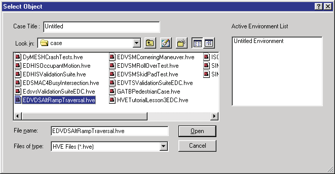 Figure 12-3: Adding Environments from previous cases.
To choose an environment from another case, perform the following steps:
- Click on Mode, Environment, Add and choose Previous. The Previous
Environment Files Selection dialog will be displayed (see Figure 12-3).
This dialog displays a list of case names for all cases in the
\casesubdirectory. - Click on a case name. The Environment Name for the selected case will be displayed.
- Press OK to add the selected environment to the current case.
Sky Attributes
Sky attributes determine the appearance of the background when a 3-D geometry file is displayed. (updated: the sky attributes are now set on the Sky tab of the Environment Information property sheet — not through a separate "Set Sky Attributes" button and dialog. The Sky tab is shown only in 3-D run modes or with a 3-D camera viewer.) The following attributes are available:
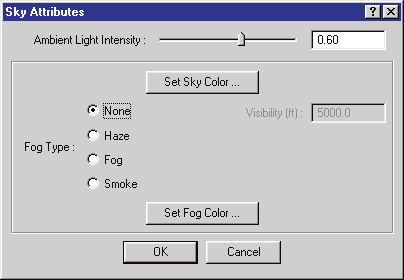 Figure 12-4: Environment Sky Attributes dialog.
- Ambient Intensity — Allows the user to determine the ambient lighting level in the scene. This attribute may be used for visualizing various levels of daylight, dusk/dawn and darkness.
- Sky Color — Allows the user to edit the current sky color, using either a color wheel or by supplying directly the red, green and blue color values.
- Fog Type — A user-selectable type of visual occlusion. The options are:
- None
- Fog
- Haze
- Smoke
NOTE: The difference in the above fog types is in the way visibility is reduced as a function of distance. None implies no reduction. Fog has a linear reduction, Haze has a quadratic reduction and Smoke has a cubic reduction. See Chapter 13, Environment Model Definition, for additional information.
- Maximum Visibility — A user-editable field defining the distance (from the camera) at which objects are no longer visible.
NOTE: Because the camera position represents the eye position of a person viewing the scene, the Maximum Visibility attribute is very useful for visibility studies!
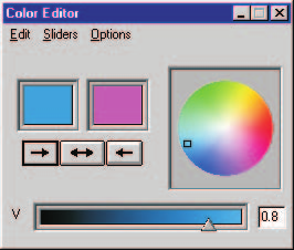 Figure 12-5: Sky Color tool for assigning the color of the sky.
To set the sky attributes, perform the following steps:
- Display the Environment Information dialog (if it is not currently displayed) by double-clicking on the Current Environment in the Environment Editor dialog.
- Select the Sky tab (see Figure 12-4). (updated: the Sky tab is available only when a 3-D camera viewer is in use; it is not present in HVE-2D.)
- Set the Ambient Light Intensity field using the slider or by typing in a number.
- Click on Sky Color to display the Set Sky Color dialog (see Figure 12-5). Set the sky color using the color wheel (move the hot spot in the color wheel) or by typing in the Red, Green and Blue color values. Press Accept to see the result in the sample window.
- Choose the desired fog type (None, Fog, Haze or Smoke).
- If a Fog Type was selected, enter the desired Maximum Visibility distance.
- Press OK to accept the current sky attributes.
Traffic Signals
(updated) The Environment Information property sheet includes a Traffic Signals tab, used to configure the timing of traffic signals placed in the environment. Like the Sky tab, it is shown only in 3-D run modes or with a 3-D camera viewer. Select a signal from the Traffic Signals list to edit its timing; the Type and Layout fields describe the selected signal, and the Is Active, Repeating and Signal Timing controls (Start Time, or Follow another signal with an Overlap) define its cycle. See the code-verified Environment Information Dialog for the full field reference.
3-D Environment Geometry
The user may supply a 3-D geometry file used for visualizing the environment. This geometry is also used by the current calculation model to provide detailed information about the surface elevation, slope and friction beneath each tire.
NOTE: If no 3-D geometry file is supplied, the current simulation model will normally assume a flat terrain with uniform friction (associated with the vehicle's individual tires; refer to the Vehicle Editor for details regarding the tire's frictional properties).
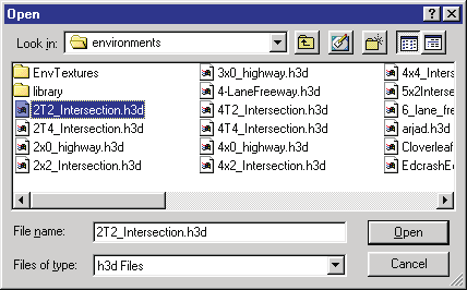 Figure 12-6: Environment File Selection dialog used for opening and saving 3-D Geometry and image files. See Table 12-1 for supported formats.
3-D Geometry information for the current case is supplied using the Files group of the Environment Information dialog. (updated: the current dialog uses a single Files group with a File Type selector — Terrain, Aerial Photo or Sky Image, depending on licensed features — in place of the separate 3-D Geometry File and Scanned Image File entries in earlier versions.) The following buttons are provided:
- New — Removes the current environment file of the selected type from the current case. (updated: any terrain, aerial or backdrop file currently in use is cleared, and aerial image coordinates are reset to their defaults.)
- Open — Allows the user to add a previously created 3-D geometry file (or image) to the current case.
- Save / Save-As — Allows the user to save the current 3-D geometry
file in the HVE
.h3dfile format.
New
To remove the current 3-D geometry or image environment file, perform the following steps:
- Display the Environment Information dialog (if it is not currently displayed) by clicking the Object Info button on the toolbar.
- Select the desired File Type and click on New.
- Press OK.
The current environment geometry and/or image will be gone.
Open
To open an environment 3-D geometry file, perform the following steps:
- Display the Environment Information dialog (if it is not currently displayed) by clicking the Object Info button on the toolbar.
- Choose Open to display the File Selection dialog (see Figure 12-6).
- Choose the format of the desired file (e.g., HVE Geometry or other supported format) using the file-type filter.
NOTE: The current format acts as a file filter for the files in the
images/environmentssubdirectory. Table 12-1 provides a list of formats and their associated extensions. The number of supported formats increases as new translators become available.
- Select the desired 3-D geometry file and press OK. The selected filename will appear in the Environment Information dialog.
- Press OK.
The selected 3-D environment will be displayed in the Environment Viewer.
Table 12-1: HVE Supported File Formats (updated to current file dialogs)
| Format | Type | Extension |
|---|---|---|
| HVE Geometry (internal format) | 3-D Geometry | .h3d |
| Inventor | 3-D Geometry | .iv |
| VRML | 3-D Geometry | .wrl |
| OBJ | 3-D Geometry | .obj |
| DXF (requires DXF translator feature) | 2-D or 3-D Geometry | .dxf |
| DWG (requires DXF translator feature) | 2-D or 3-D Geometry | .dwg |
| Bitmap | 2-D Image | .bmp |
| TIFF | 2-D Image | .tif |
| GIF | 2-D Image | .gif |
| RGB | 2-D Image | .rgb |
| JPEG | 2-D Image | .jpg |
(updated: JPEG support has been added; 3D Studio import listed in some older editions is handled via the DXF/translator features. Image formats are used for Aerial Photo and Sky Image file types.)
Save-As
To save the current environment as a new 3-D geometry file, perform the following steps:
- Display the Environment Information dialog (if it is not currently displayed) by clicking the Object Info button on the toolbar.
- Choose Save-As to display the File Selection dialog.
- Enter a name for the file.
NOTE: HVE automatically appends its own
.h3dextension. Texture pathnames are stored relative to the HVEenvtexturesdirectory.
- Press OK to save the file.
- Press OK to close the Environment Information dialog.
The selected 3-D environment will be displayed in the Environment Viewer.
3-D Geometry File Options
Most popular CAD packages use a conventional coordinate system in which the Z-axis points up. HVE uses the coordinate system adopted by the Society of Automotive Engineers (see Appendix III). In this coordinate system, the Z-axis points down (in the direction of gravity). In addition, users may have created their geometry files using meters, feet, or any other unit of length. In HVE, program units for length are always inches (user units, however, may be anything the user desires).
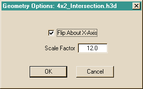 Figure 12-7: Geometry File Options dialog, used for flipping over the environment (HVE requires the Z-axis to point down) and for scaling the environment (HVE requires internal units of inches).
The Geometry File Options dialog allows the user to perform these simple conversions. (updated: this dialog is displayed automatically when opening a terrain geometry file — the axis flip and scale entries apply chiefly to DXF files, and the dialog also offers the option to use the opened file as the default environment.) Perform the following steps:
- Open a 3-D Geometry file, as described on the previous pages. The Geometry Options dialog is displayed (see Figure 12-7).
- Click Flip About X-Axis to make the Z-axis point down.
- Enter the Scale Factor required to convert your drawing units to inches. For example, if your drawing is in feet, the conversion factor is 12.0; if your drawing is in meters, the conversion factor is 39.37.
- Press OK. The Geometry File Options dialog is removed.
- Press OK. The environment geometry is flipped and scaled, and the result is displayed in the Environment Viewer.
Environment Image File Subdirectory
All environment image files, whether 3-D geometry or 2-D images, are found
in the \images\environments subdirectory.
NOTE: If you use another tool to create a 2-D image or 3-D geometry file, you must copy the file to the
\images\environmentssubdirectory in order for HVE to find it. See Appendix I for more information.
Scanned Photographs
A scanned photograph (a 2-D image, or bitmap) may be used to visualize the environment. Using a scanned photograph is a very quick and convenient way to provide a realistic environment background or sky. (updated: the current Environment Information dialog distinguishes two image uses — an Aerial Photo, displayed on a ground polygon at user-entered ground coordinates, and a Sky Image, used as a fixed backdrop. The discussion below applies to the Sky Image/backdrop use.)
NOTE: Scanned photographs are created using a scanner or a digital camera.
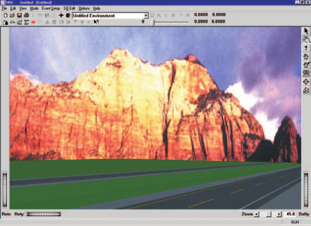 Figure 12-8: Example of a 3-D Geometry file used as the foreground and a scanned image used as the background and sky.
Scanned photographs differ in an important and fundamental way from 3-D geometry files: they are a fixed, 2-D image. The image is not affected by manipulating the viewer thumbwheels or changing the view using the Set Camera dialog.
NOTE: The key to using a scanned accident site image is to use the Set Camera dialog to assign the same camera position, picture center and camera focal length as were used to take the original picture. This process links the view of the photograph to the view of the simulation.
NOTE: If you do not know the exact location from which the photograph was taken, you can use the viewer thumbwheels (along with a little trial and error!) to figure out the correct camera location.
In addition, a scanned photographic image provides no physical information (elevation, slope, friction) to the current calculation model.
To add a scanned background image, perform the following steps:
- Display the Environment Information dialog (if it is not currently displayed) by clicking the Object Info button on the toolbar.
- Select the Sky Image file type and choose Open to display the File Selection dialog.
- Choose the format of the desired file (e.g., BMP, TIFF, JPEG or other supported image format). The Environment File Selection dialog is displayed, showing all the environment images of the selected file format.
NOTE: HVE automatically distinguishes between 3-D geometry formats and image formats. Table 12-1 provides a list of formats, file types and their associated extensions.
- Select the desired scanned image file from the list box and press OK. The selected filename will appear in the Environment Information dialog.
- Press OK to display the current environment scanned image.
An example of a sky bitmap and 3-D geometry terrain is shown in Figure 12-8.
NOTE: Both a 3-D Geometry file and a scanned photograph may be selected. Scanned images are always placed behind the 3-D geometry. Thus, you can provide a photograph for the visual effect and the 3-D geometry file for the physical information.
NOTE: Scanned images make great skies. The RGB format includes several pre-defined skies for your use. See Figure 12-8 for an example of this effect.
NOTE: If a scanned photograph is used, the view is fixed! This means that the user may attach the camera only to the environment, and not to any of the humans or vehicles.
NOTE: If a scanned image is used for the road surface, you should confirm the scanned image was imported at the correct scale. The best way to do this is to identify some known landmarks in the viewer (you'll need to know the actual distance between these landmarks), then perform a simple simulation test to confirm that it takes the vehicle the correct time to travel between the landmarks. (updated: the Aerial Photo file type addresses this directly — the Aerial Image dialog asks for the upper-left and lower-right ground coordinates of the image, which fixes the scale.)
Overlays
Each 3-D geometry object (road surface, trees, delineation, etc.) has an overlay name (see the 3-D Editor documentation for additional information about overlay names). The Overlays option in the View menu displays a list containing every overlay name, as shown in Figure 12-9. By selecting or deselecting an overlay name, the user can decide whether an object is displayed in the viewer.
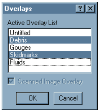 Figure 12-9: The Display Overlays dialog allows the user to select and deselect overlays.
NOTE: If you deselect an overlay, its 3-D surface data (elevation, slope and friction) are still supplied to the current calculation model. One option is to include both a scanned photograph and a 3-D geometry file with all the overlays deselected. That way, the simulation will include the 3-D surface information, but the view will be from a photograph.
To display or remove selected overlays, perform the following steps:
- Choose Overlays from the View menu. The Overlays dialog will be displayed, showing a list box with all the overlay names in the current scene. The currently selected overlays will be highlighted.
- Select additional overlays you wish to be displayed, and deselect those overlays you wish to remove.
- Click on the Scanned Image Overlay check box to display or remove any scanned environment image.
- Press OK when the desired overlays and scanned image have been selected.
Editing the Current Environment
After a new or previous environment has been created, it may be edited. To edit the current environment, perform the following steps:
- Click on the Object Info button on the toolbar. The Environment Information dialog will be displayed.
- Edit any of the available fields to update the physical environment, as described earlier in this chapter.
- Select the Sky tab to update the sky attributes, as described under Sky Attributes.
- Click on New, Open or Save-As to update the environment 3-D Geometry, aerial photo or scanned image file, as described under 3-D Environment Geometry.
- Press OK to update the current environment.
See also (code-verified dialog references): Environment Information Dialog · Environment Material Properties · Surface Editor
← Previous: Section Five — Environment Editor | Index | Next: Chapter 13 — Environment Model Definition →