Chapter 30 — Brake Temperature Model
Updated Markdown edition of the HVE User's Manual (HVE Version 5, Seventh
Edition, January 2006), Chapter 30, pages 30-1 through 30-16. Verified against the current HVE application source
(HVEINV-64/BrakeDesignMaterialProperties.cpp and the brake model in
HveBrakes.cpp); see also the code-verified
Brake Designer Material Properties dialog reference.
Overview
During braking, the vehicle's kinetic energy is converted into heat energy by the wheel brake assemblies. This energy causes a temperature rise in the brake assembly components (linings and rotor or drum) that is dissipated into the atmosphere through conduction and convection.
The modeling procedure used in the HVE Brake Temperature Model was adapted from the lumped mass method proposed by MacAdam, et al [4.2]. This chapter describes how brake temperatures are calculated. This description involves four subjects:
- Modeling Technique
- Model Inputs
- Model Outputs
- Equations
Temperature change affects the performance of the wheel brake assemblies by expansion of the components and by altering the friction of the lining material. Therefore, the HVE Brake Designer (see Chapter 29) includes the temperatures calculated by this model as an independent input to the equations for brake torque.
Modeling Technique
Calculating the temperature of brake system components is a classic heat flow problem. \(\dot{H}\), the rate of work (heat energy) into the system is:
In the case of a wheel brake assembly, the rate of work at any instant is:
This energy is absorbed into the brake linings and drum/rotor through conduction, stored through capacitance and removed through convection.
NOTE: Radiant heat transfer is considered negligible for the range of temperatures encountered and, thus, is not considered by the model.
Using a lumped mass model, the rotor/drum is divided into 10 nodes across its thickness, the lining is one node and the lining and rotor or drum exterior surfaces each represent a node. Thus, the model includes a total of 13 nodes at which the temperature may be calculated (see Figure 30-1). Associated with each node are its thermal parameters: conductivity, convectivity and heat capacitance. At any instant the First Law of Thermodynamics (i.e., an energy balance) may be expressed as:
where
| Symbol | Description |
|---|---|
| \([M]\) | Capacitance matrix |
| \(\left[\frac{dT}{dt}\right]\) | Thermal rate matrix |
| \([S]\) | Internal Temperature Coefficient matrix |
| \([T]\) | Temperature matrix |
| \([C]\) | Boundary condition conductivity matrix |
| \(T_{L/D}\) | Interface temperature |
| \([D]\) | Boundary condition convectivity matrix |
| \(T_A\) | Ambient temperature |
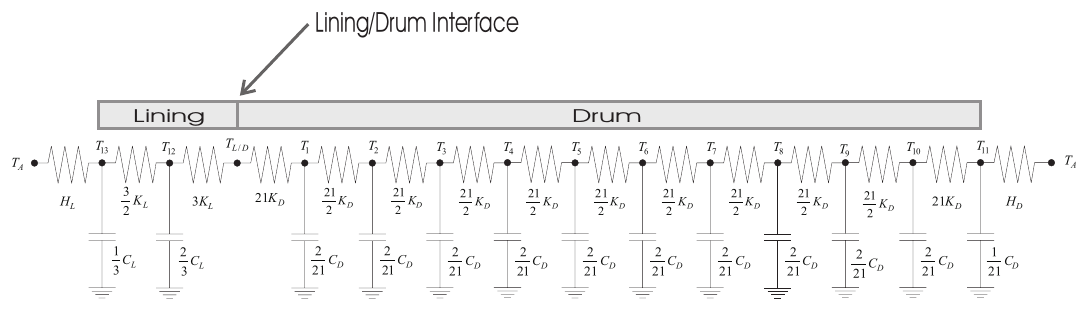 Figure 30-1 — Representation of the 13-node lumped parameter brake
temperature model [4.2]: ambient air — lining exterior surface node T₁₃ —
lining node T₁₂ — lining/drum interface T_L/D — drum/rotor nodes T₁ … T₁₀ —
drum/rotor exterior surface node T₁₁ — ambient air, with conductances
(3/2 K_L, 3K_L on the lining side; 21K_D, 21/2 K_D between drum nodes),
convection coefficients H_L and H_D at the exposed surfaces, and nodal
capacitances (C_L/3, 2C_L/3 for the lining; 2C_D/21 for interior drum nodes
and C_D/21 at the drum surface).
Figure 30-1 — Representation of the 13-node lumped parameter brake
temperature model [4.2]: ambient air — lining exterior surface node T₁₃ —
lining node T₁₂ — lining/drum interface T_L/D — drum/rotor nodes T₁ … T₁₀ —
drum/rotor exterior surface node T₁₁ — ambient air, with conductances
(3/2 K_L, 3K_L on the lining side; 21K_D, 21/2 K_D between drum nodes),
convection coefficients H_L and H_D at the exposed surfaces, and nodal
capacitances (C_L/3, 2C_L/3 for the lining; 2C_D/21 for interior drum nodes
and C_D/21 at the drum surface).
This matrix equation is solved for \([T]\), the temperature at each node, at each integration timestep. The outputs of interest are \(T_5\) (the temperature at the interior of the drum or rotor), \(T_{L/D}\) (the temperature at the interface between the lining and drum or rotor), and \(T_{12}\) (the temperature at the interior of the lining). The specific model inputs, outputs and solution procedure are described below.
Model Inputs
The inputs to the lumped mass model are:
- Drum Diameter (Drum Brake), \(D_D\) — Inside diameter of the brake drum. The torque radius (half the drum diameter) is the lever arm of the force applied by the brake lining.
- Rotor Inner and Outer Diameter (Disc Brake), \(D_i\), \(D_o\) — Rotor outer and inner diameter. The torque radius is defined as the midpoint between the inner and outer radii.
- Lining Width (Drum Brake), \(W_L\) — Width of the rubbing surface in the inside diameter of the drum.
- Included Angle (Disc Brake), \(\gamma_L\) — Pad included angle. The included angle and inner and outer diameter define the pad contact surface area with the rotor.
- Drum/Rotor Specific Heat, \(C_{pD}\) — Specific heat of the drum or rotor material.
- Drum/Rotor Material Density, \(\rho_D\) — Density of the drum or rotor.
- Drum/Rotor Conduction Coefficient, \(K_D\) — Coefficient of thermal conduction for the drum or rotor material.
- Drum/Rotor Convection Coefficients, \(H_{0D}\), \(H_{1D}\) — Coefficients of thermal convection at the drum or rotor interface with the surrounding air. The first coefficient, \(H_{0D}\), is the static convection coefficient; the second coefficient, \(H_{1D}\), is the velocity-dependent convection coefficient to account for the effect of vehicle velocity on convective heat transfer.
- Lining Specific Heat, \(C_{pL}\) — Specific heat of the brake shoe or pad lining material.
- Lining Mass, \(M_L\) — Mass of the brake shoe or pad lining material, calculated from the product of the volume and material density.
- Lining Conduction Coefficient, \(K_L\) — Coefficient of thermal conduction for the brake shoe or pad lining material.
- Lining Convection Coefficients, \(H_{0L}\), \(H_{1L}\) — Coefficients of thermal convection at the brake lining material interface with the surrounding air. The first coefficient, \(H_{0L}\), is the static convection coefficient; the second coefficient, \(H_{1L}\), is the velocity-dependent convection coefficient to account for the effect of vehicle velocity on convective heat transfer.
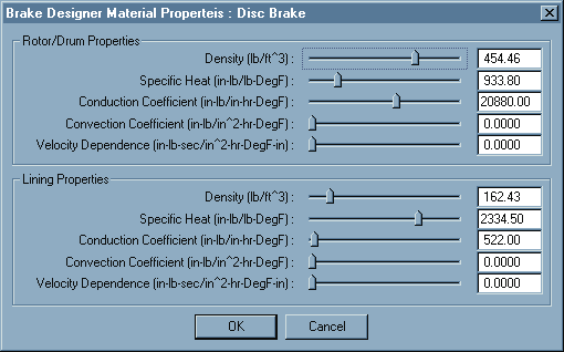 Figure 30-2 — Brake Material Properties dialog. Default material properties
are assigned for cast iron drums and rotors, and common lining friction
materials. (See the dialog reference page.)
Figure 30-2 — Brake Material Properties dialog. Default material properties
are assigned for cast iron drums and rotors, and common lining friction
materials. (See the dialog reference page.)
These parameters, shown in Table 30-1, are assigned using the HVE Brake Designer dialogs (see Figures 29-10 through 29-17) and the Brake Material Properties dialog (see Figure 30-2).
The remaining independent parameters for the brake temperature model are assigned by the user during event set-up:
- Environment Ambient Temperature, \(T_A\) — Ambient temperature, assigned using the Environment Information dialog (see Section Five).
- Initial Rotor/Drum Temperature, \(T_{0D}\) — Temperature of the drum or rotor at the start of the simulation, assigned using the Event Editor.
- Initial Lining Temperature, \(T_{0L}\) — Temperature of the lining at the start of the simulation, assigned using the Event Editor (see Section Six).
NOTE: See Table 29-2 for parameter definitions related to shoe and rotor/drum geometry.
Table 30-1 — Brake Material Properties
| Parameter | Unit Name | Description |
|---|---|---|
| Rotor/Drum Material Density | UtVehDensity | Density of rotor or drum material (used for calculating the mass of the rotor or drum) |
| Rotor/Drum Specific Heat | UtVehSpecificHeat | Change in enthalpy of the brake rotor or drum material with respect to temperature at constant pressure |
| Rotor/Drum Conduction Coefficient | UtVehConduction | Energy transfer coefficient through the brake rotor or drum material |
| Rotor/Drum Convection Coefficient | UtVehConvection | Static convective energy transfer coefficient between the brake rotor or drum surface and adjacent air |
| Rotor/Drum Velocity-Dependent Convection Coefficient | UtVehConvectionVel | Velocity-dependent energy transfer coefficient between the brake rotor or drum surface and adjacent air (i.e., this coefficient is multiplied by vehicle linear velocity to determine the convection rate) |
| Lining Material Density | UtVehDensity | Density of lining material (used for calculating the mass of the pads or shoe linings) |
| Lining Specific Heat | UtVehSpecificHeat | Change in enthalpy of the brake lining material with respect to temperature at constant pressure |
| Lining Conduction Coefficient | UtVehConduction | Energy transfer coefficient through the brake lining material |
| Lining Convection Coefficient | UtVehConvection | Static convective energy transfer coefficient between the brake lining surface and adjacent air |
| Lining Velocity-Dependent Convection Coefficient | UtVehConvectionVel | Velocity-dependent energy transfer coefficient between the brake lining surface and adjacent air (i.e., this coefficient is multiplied by vehicle linear velocity to determine the convection rate) |
NOTE: Drum Diameter, Rotor Inner and Outer Diameter, Lining Width and Included Angle are defined in Chapter 29, HVE Brake Designer.
Model Outputs
The outputs from the model are:
- Lining Exterior Surface Temperature, \(T_{LS}\) — Temperature at the interface between the lining and the outside air (node 13).
- Lining Internal Temperature, \(T_L\) — Internal lining temperature 1/3 of the distance from the interface to the lining exterior (node 12).
- Interface Temperature, \(T_{L/D}\) — Temperature at the interface between the lining and drum or rotor. This point is important as it represents the location where heat energy is introduced into the system (see Figure 30-1).
- Rotor/Drum Internal Temperature, \(T_D\) — Internal temperature of the rotor or drum at node 5.
- Exterior Rotor/Drum Temperature, \(T_{DS}\) — Temperature at the rotor or drum interface with the outside air (node 1). (Per the node layout in Figure 30-1, the drum exterior surface is the last drum node, node 11.)
\(T_L\), \(T_{L/D}\) and \(T_D\) are available in the Vehicle Output Tracks, Wheel Group (Key Results or Variable Output; see Chapter 15, Event Model).
Model Equations
The fundamental equations for the solution of \(T_{L/D}\) and \(T_N\) were shown earlier in matrix form (see eq. 30-3). The following sections provide details for the calculation of the interface temperature and matrix coefficients.
Interface Temperature
The temperature at the interface between the lining and drum/rotor is:
where \(T_{D_1}\) is the temperature of the drum/rotor node adjacent to the interface (node 1) and \(T_{D_{10}}\) (as printed in the original) refers to the temperature of the lining node adjacent to the interface (node 12 in Figure 30-1).
Capacitance Matrix, M
The thermal capacitance coefficients are calculated as follows:
Rotor/Drum
where
| Symbol | Description |
|---|---|
| \(C_D\) | Capacitance coefficient for rotor or drum |
| \(C_{PD}\) | Specific heat of rotor or drum material |
| \(\rho_D\) | Density of rotor or drum material |
| \(V_D\) | Volume of rotor or drum |
where \(D_o\) = rotor outer diameter, \(D_i\) = rotor inner diameter and \(x_D\) = rotor thickness;
where \(D_D\) = drum diameter, \(W_L\) = lining width and \(x_D\) = drum thickness.
Lining
where
| Symbol | Description |
|---|---|
| \(C_L\) | Capacitance coefficient for lining |
| \(C_{PL}\) | Specific heat of lining material |
| \(\rho_L\) | Density of lining material |
| \(V_L\) | Volume of lining material |
where \(\gamma_L\) = pad arc length (deg), \(D_o\) = outer rotor diameter, \(D_i\) = inner rotor diameter and \(x_D\) = pad thickness; and
where \(\alpha_{o,Pri}\) = arc length of primary shoe (deg), \(\alpha_{o,Sec}\) = arc length of secondary shoe (deg), \(D_D\) = drum diameter, \(W_L\) = lining width and \(x_D\) = lining thickness.
Using these capacitance coefficients, \(C_D\) and \(C_L\), the capacitance matrix, \(M\), for the 13-node lumped mass model is the diagonal matrix:
(the first ten diagonal entries, for the interior drum/rotor nodes, are \(\tfrac{2}{21}C_D\); the eleventh, for the drum/rotor exterior surface node, is \(\tfrac{C_D}{21}\); the twelfth, for the lining node, is \(\tfrac{2}{3}C_L\); and the thirteenth, for the lining exterior surface node, is \(\tfrac{C_L}{3}\)).
Internal Temperature Coefficient Matrix
The internal temperature coefficient matrix is composed of both conduction and convection coefficients. The conduction coefficients are calculated as follows:
Rotor/Drum
where
| Symbol | Description |
|---|---|
| \(K_D\) | Conductivity coefficient of rotor or drum |
| \(k_D\) | Conductivity of rotor or drum material |
| \(A_D\) | Heat transfer area of rotor or drum |
| \(x_D\) | Thickness of rotor or drum |
where \(D_o\) = rotor outer diameter and \(D_i\) = rotor inner diameter;
where \(D_D\) = drum diameter and \(W_L\) = lining width.
Lining
where
| Symbol | Description |
|---|---|
| \(K_L\) | Conductivity coefficient for lining |
| \(k_L\) | Conductivity of lining material |
| \(A_L\) | Heat transfer area of lining |
| \(x_L\) | Thickness of lining |
where \(\gamma\) = included pad angle, \(D_o\) = outer rotor diameter and \(D_i\) = inner rotor diameter; and
where \(\alpha_{o,Pri}\) = included angle of primary shoe, \(\alpha_{o,Sec}\) = included angle of secondary shoe, \(D_D\) = drum diameter and \(W_L\) = lining width.
The convection coefficients are calculated as follows:
Rotor/Drum
where
| Symbol | Description |
|---|---|
| \(H_D\) | Convectivity matrix coefficient for rotor or drum |
| \(H_{0D}\) | Convection coefficient for rotor or drum |
| \(H_{1D}\) | Velocity-dependent convection coefficient |
| \(V\) | Vehicle linear velocity |
| \(A_D\) | Convective surface area for rotor or drum (same as previously defined rotor or drum area) |
Lining
where
| Symbol | Description |
|---|---|
| \(H_L\) | Convectivity matrix coefficient for pad or lining |
| \(H_{0L}\) | Convection coefficient for pad or lining |
| \(H_{1L}\) | Velocity-dependent convection coefficient |
| \(V\) | Vehicle linear velocity |
| \(A_L\) | Convective surface area for pad or lining (same as previously defined pad or lining area) |
(The original printing of eq. 30-10 shows "\(H_{1D}\)" inside the parentheses; the lining velocity-dependent coefficient \(H_{1L}\) is intended, as defined in the symbol list.)
The internal temperature coefficient matrix for the 13-node lumped mass model is the tridiagonal matrix:
Rows 1 through 10 form the drum/rotor conduction chain; row 11 is the drum/rotor exterior surface node, which includes the drum convection loss term; rows 12 and 13 are the lining node and lining exterior surface node, the latter including the lining convection loss term \(H_L\). (The original printing shows "\(-21K_D - H_L\)" in row 11; the drum surface convection coefficient \(H_D\) is intended there.)
Internal Temperature Matrix, T
\(T\) is a matrix of dependent temperature results for each of the 10 rotor (or drum) nodes, the lining node and the two surface nodes. The \(T\) matrix is as follows:
The \(T\) matrix contains the brake model outputs:
- Lining Temperature, \(T_{12}\) — Temperature at node 12, 1/3 of the distance from the interface to the lining exterior.
- Rotor/Drum Temperature, \(T_5\) — Temperature at node 5, approximately half way from the interface to the rotor/drum exterior.
Boundary Condition C Matrix
The boundary condition \(C\) matrix provides the heat conduction coefficients for the drum and lining. The conduction coefficients were defined earlier; see eq. 30-7 for the rotor/drum conduction coefficients and eq. 30-8 for the lining conduction coefficients.
The resulting matrix for the 13-node lumped mass model is as follows:
(the interface heat input enters the system at drum node 1 and lining node 12, the two nodes adjacent to the lining/drum interface).
Boundary Condition D Matrix
The boundary condition \(D\) matrix provides the heat convection coefficients between the drum and lining and the surrounding air. The convection coefficients were defined earlier; see eq. 30-9 for the rotor/drum convection coefficients and eq. 30-10 for the lining convection coefficients.
The resulting matrix for the 13-node lumped mass model is as follows:
(convective losses to ambient air occur at the drum/rotor exterior surface, node 11, and the lining exterior surface, node 13; the original printing shows these entries as "\(K A_D\)" and "\(K A_L\)", i.e., the convection coefficient times the surface area, which is the definition of \(H_D\) and \(H_L\) in eqs. 30-9 and 30-10).
Solution Procedure
The \(M\), \(S\), \(T\), \(C\) and \(D\) matrices are used in the solution for the current temperature matrix, \(T\). Eq. 30-3, defined earlier, is rearranged by inverting the \(M\) matrix. Then, three new working matrices are defined:
where \([M]^{-1}\) is the inverted \([M]\) matrix.
Rearranging eq. 30-3 to solve for \(\left[\frac{dT}{dt}\right]\) yields:
where
| Symbol | Description |
|---|---|
| \(\left[\frac{dT}{dt}\right]\) | Time rate of change in temperature |
| \([T_{Prev}]\) | Temperature at each node during the previous timestep |
Finally, the current temperature at each node can be calculated:
where
| Symbol | Description |
|---|---|
| \(\Delta t\) | Integration timestep |
The resulting temperature at nodes 5 and 12 (internal drum and lining temperatures, respectively) and the temperature at the lining/drum (or pad/rotor) interface are available in the output tracks (Wheels Group). In addition, the lining temperature is used (along with the current wheel spin velocity) by the wheel brake torque calculations (see Chapter 29) to assign the current lining friction coefficient.
← Previous: Chapter 29 — HVE Brake Designer | Index | Next: Chapter 31 — Antilock Braking Systems →