DyMESH Version 3
DyMESH Version 3 (Engineering Dynamics Company, 2026 HVE Forum) adds a collision model for the vehicle wheels — DyMESH Wheels — so that impact forces and moments developed at the tires/wheels are computed and fed into the vehicle dynamics. Version 3 also finalizes the user-defined third-order force-deflection stiffness described in the Collision Model chapter.
Problem statement
- DyMESH Version 2 calculated 3-D collision forces and moments only for the sprung mass (the vehicle body).
- However, significant collision forces and moments can occur during impact at the wheel(s) — e.g. an angled wheel-to-wheel or wheel-to-body strike.
- Ignoring these forces affects the collision dynamics (post-impact heading, spin, and trajectory).
Solution criteria
The wheel collision model had to:
- Calculate forces and moments from the collision at each individual wheel.
- Integrate the results directly into the equations of motion.
- Be robust, accounting for:
- Wheel shape — a round cylinder.
- Wheel location / displacement (the wheel can be moved by the impact).
- Wheel steering and camber change.
- Wheel spin (tangential friction).
Solution
The wheel model reuses the DyMESH machinery by treating each wheel as its own DyMESH body:
- Treat each wheel as an independent DyMESH object.
- Create the wheel mesh based on tire size. In the code
(
InitializeDyMeshWheels/calcWheelMeshinDymesh.cpp) a cylindrical wheel mesh is built from the tire radius and width, withNUM_DYMESH_WHEEL_INC(80) angular increments. Wheel material stiffnesses are set to their own constants —TRUCK_WHEEL_A_STIFF/TRUCK_WHEEL_B_STIFF(500 / 100) orPASS_CAR_WHEEL_A_STIFF/PASS_CAR_WHEEL_B_STIFF(250 / 50) — and a saturation deflection tied to the wheel half-width is assigned per vertex (deflMax). - Place transforms in front of and following the DyMESH calculation to carry the wheel's location, steer, camber, and spin into and out of the collision computation.
- The user can select individual wheels for analysis (for computational efficiency — only the wheels expected to be involved need be simulated).
Flow charts
Version 3 adds a wheel loop nested within the existing sprung-mass collision loop.
Sprung Mass loop — for each pair of vehicles:
- Collision Test → if no collision, skip.
- Swap Vehicles (assign Master / Slave).
- Get Vehicle Matrices.
- DyMESH (Master, Slave) — the body-to-body collision.
- DyMESH Wheels (Master, Slave) — the wheel collisions.
- Smooth Collision Pulse.
- Separation Test.
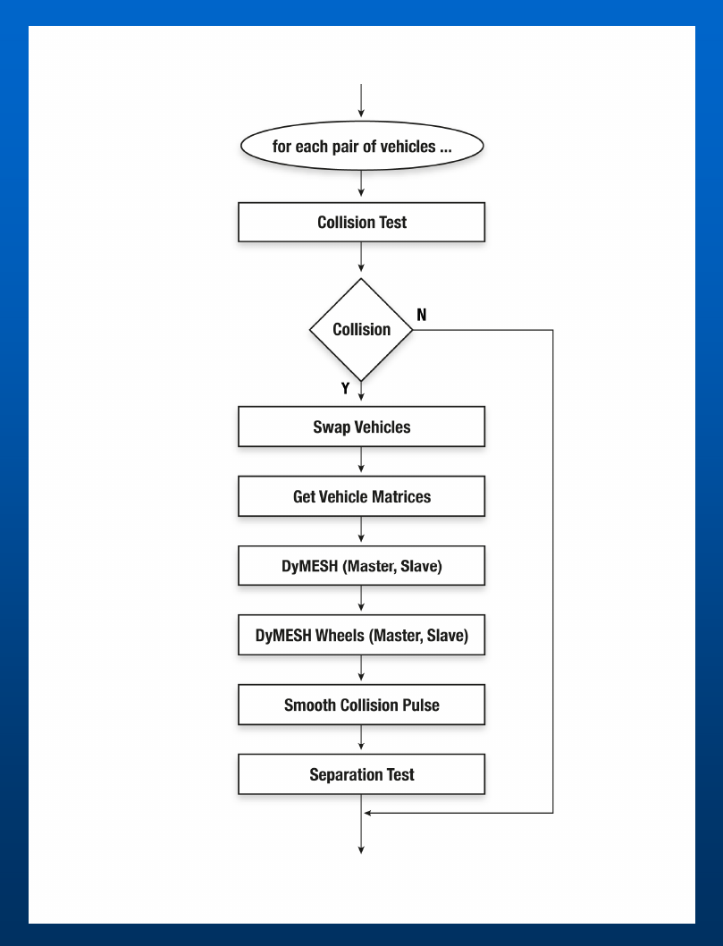 Figure: Sprung Mass flow chart.
Wheel loop — for each wheel:
- Collision? → if no, skip.
- Get Wheel Matrices.
- Update Wheel Mesh (apply location/steer/camber/spin transform).
- DyMESH (Master, Slave) — run the contact algorithm on the wheel mesh.
- Add Wheel Force to Sprung Mass.
- Update Wheel Mesh Damage.
- Calculate Wheel Displacement.
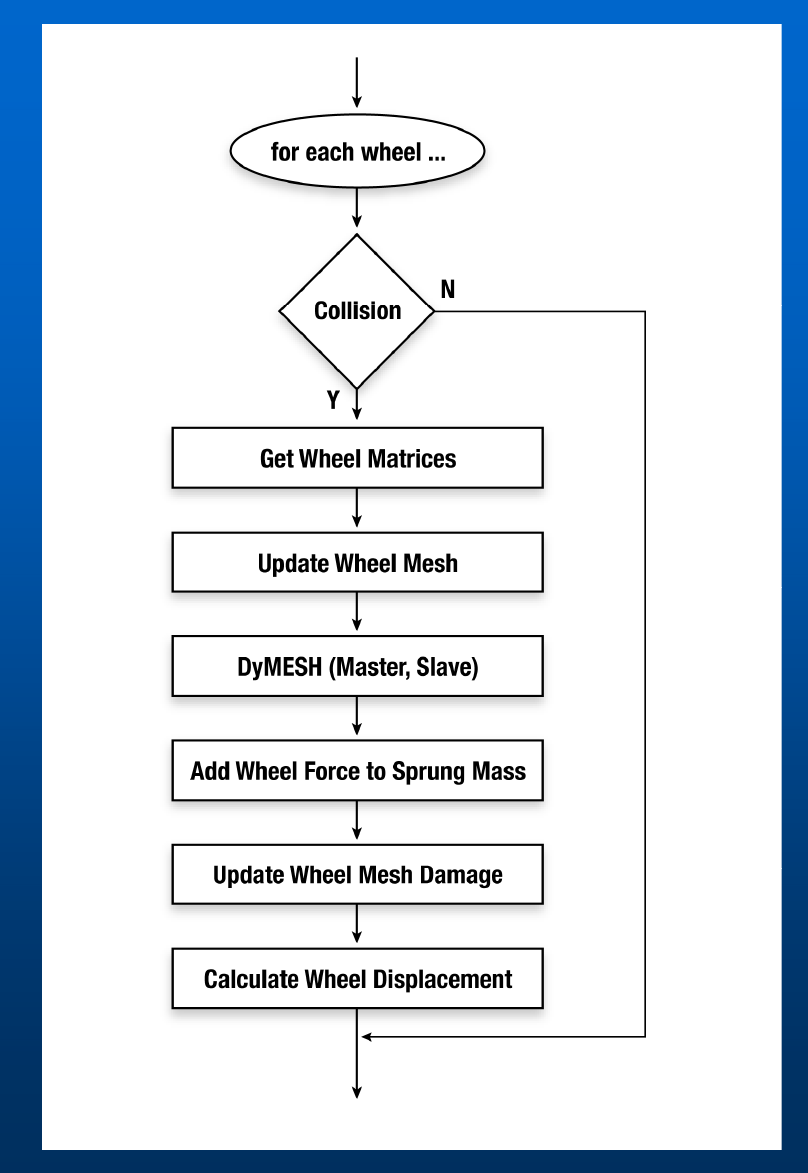 Figure: Wheels flow chart.
(updated: In the current code these steps are implemented in
Physics/Source/Simon/PHYMODEL.CPP as DyMeshWheels(), UpdateWheelMesh(),
AddWheelForceToSprungMass(), UpdateWheelMeshDamage(), and
DyMeshWheelDispl().)
DyMESH Wheels user interface
The wheel model is driven by three areas of the interface: the DyMESH Options, the per-wheel Set-up, and the Output vs. Time results.
DyMESH Options dialog
The DyMESH Options dialog (Options menu) as shown in the deck contains:
- Use DyMESH (master enable).
- Include Environment — also run DyMESH contact against the environment (see Wheel vs. Environment for the wheel side of this feature and the tire-model handoff).
- Force To x-y Plane — constrain the collision deformation/force to the horizontal plane.
- Search — Automatic (use the calculated box size) or Set Box Size (use a user-entered box size, e.g. 20.00 in).
- Force Smoothing — Version 1 or Version 2.
- Timesteps — Use DyMESH Time Intervals, with Vehicle Trajectory (e.g. 0.0010 s) and Output Time Interval (e.g. 0.0200 s).
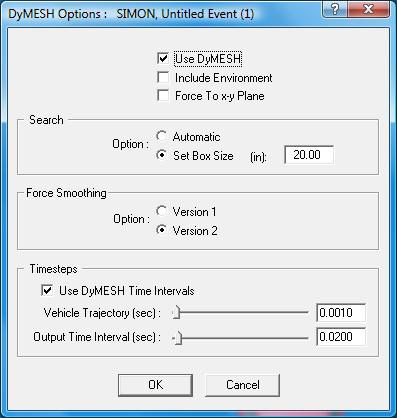 Figure: "DyMESH Options" dialog.
(updated: The current CDyMeshOptionsDlg differs from the deck screenshot. The
General area now also carries a DyMESH Version No selector — radio buttons
Version 3 and Version 4 — a Tow Vehicle / Trailer Contact checkbox
(DyMeshGeometryConnection), and separate DyMESH start time and
Environment start time fields. The Force Smoothing radio labels have been
renamed to "Version 1 and 2" and "Version 3 and Later". The stand-alone
Timesteps group shown in the deck is commented out in the current dialog
code. An Advanced tab exposes the low-level search controls — Stop After
one/two/all vertices, inside-vehicle test (master normal vs. CG), inside-polygon
test (sub-areas vs. cross product), pushback method, "don't deform a single
vertex", and "don't restore a large distance".)
Set-up (Wheels)
Each wheel is configured on the Damage tab of the Wheel Data dialog: Axle No., Side (Left / Right), Wheel is Damaged, Auto Start, Start Time, Duration (e.g. 0.1 s), and Peak Lock-up Torque. A Use DyMESH section supplies the wheel force-deflection and moment-deflection parameters:
| Parameter | Example | Meaning |
|---|---|---|
| Max No-Damage Force | 3000 lb | Force threshold below which the wheel is not permanently displaced |
| Displacement Rate | 300 lb/in | Force per unit wheel displacement (stiffness) |
| Max Force | 30000 lb | Saturation force |
| Max No-Damage Moment | 3000 ft-lb | Moment threshold below which no permanent reorientation |
| Moment Displacement Rate | 300 ft-lb/deg | Moment per unit angular change |
| Max Moment | 30000 ft-lb | Saturation moment |
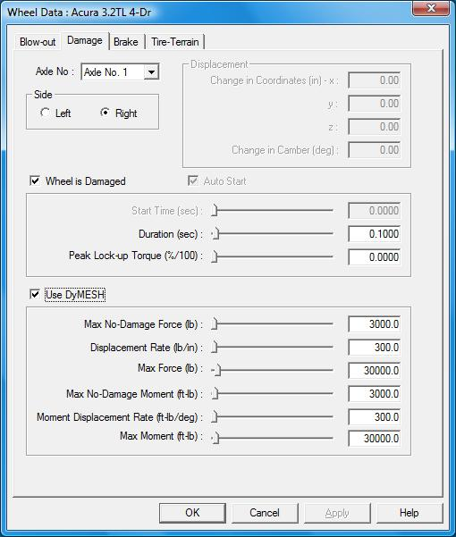 Figure: "Wheel Data" dialog, Damage tab, with the Use DyMESH force/moment fields highlighted.
See also the wheel-data / wheel-displacement inputs documented in
../../05-tires-wheels/WheelsDlg1.md.
Output vs. time
The Key Results output reports, per wheel, the collision impulses and moments in
addition to the usual kinematics and kinetics — e.g. for "Axle 1, Right":
Fx Imp, Fy Imp, Fz Imp (lb) and Mx Imp, My Imp, Mz Imp (ft-lb),
alongside the whole-vehicle (Kinetics) impulses. This lets the user see how much
of the collision load each wheel carried.
 Figure: "Key Results" output table highlighting the per-wheel impulse rows.
Wheel displacement capping (updated)
(updated: The current code adds a refinement not present in the 2026 decks. In
PHYMODEL.CPP, UpdateWheelMeshDamage() now tracks the largest actual movement
of any wheel-mesh vertex during contact, MaxContactDispl (the magnitude of the
damaged-minus-undamaged vertex displacement). DyMeshWheelDispl() then caps
the computed permanent wheel displacement by that physical contact motion: the
force-derived displacement Displ = (Ftotal - FConst)/FLinear is limited by
Displ = min(Displ, MaxContactDispl), and the per-time-step change in the x/y
wheel displacement is likewise scaled so it cannot exceed MaxContactDispl. This
prevents the wheel from being "bent" further than the collision physically moved
it. See commits 12131c2 / 16a1825, "Cap DyMesh wheel displacement by contact
motion.")
Validation
Validation is described as under way, starting from the initial conceptual design (see the Dial Engineering white-paper presentation at the 2012 HVE Forum), covering vehicle-to-vehicle collisions and other configurations.
Examples
The deck shows the wheel model applied to: an intersection collision, a truck tractor, a trailer under-ride, and (memorably) monster trucks. The main technical deck additionally shows angled collisions — a Ford pickup vs. Explorer on a graded road, and the RICSAC 1 (20 mph) and RICSAC 2 (32 mph) staged tests — as sample DyMESH validations.
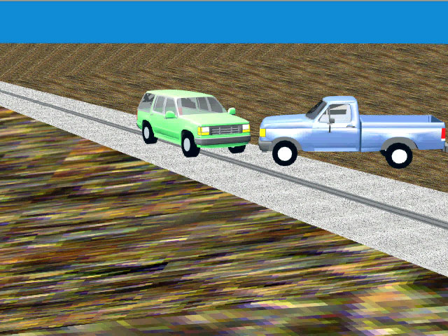 Figure: Angled collision, Ford pickup vs. Explorer.
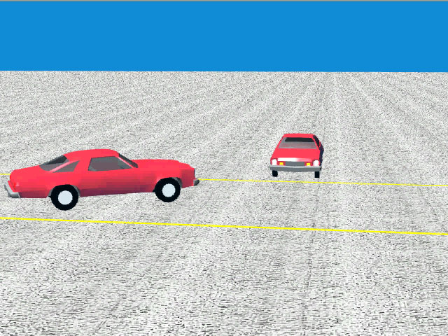 Figure: RICSAC 1 (20 mph) angled collision.
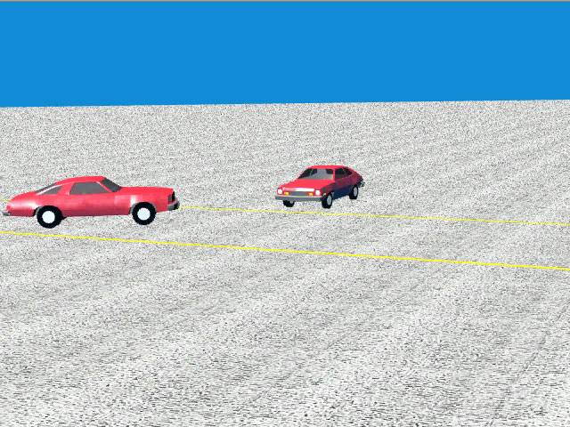 Figure: RICSAC 2 (32 mph) angled collision.
Summary
- DyMESH Wheel Impact is robust.
- Clean integration into the existing vehicle dynamics model (SIMON).
- More validation is needed.
- Initially released as a Beta option, now included in the commercial release.
Source: DyMESH Version 3 (2026 HVE Forum) — organized and verified against DYMESH.H / Dymesh.cpp, 2026-07-05.
← Previous: DyMESH Collision Model | Index | Next: DyMESH — Facts of Life →