Chapter 11 — Vehicle Model Definition (Part B: Exterior)
This part covers the vehicle exterior: the exterior dimensions (CG to Front, Right Side, Back, Left Side, Top and Bottom) and the exterior structural stiffness coefficients. These properties are edited by clicking on the exterior spheres displayed on the vehicle in the Vehicle Viewer.
Vehicle Exterior Dimensions
The vehicle's exterior dimensions are defined by its overall length and overall width. The user may choose to edit these dimensions using the Vehicle Dimensions dialogs (CG to Front, Right Side, Back, Left Side, Top, Bottom).
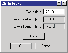 Figure 11-19: Vehicle Exterior Dimensions dialogs allow the user to view and edit the dimensions from the CG to the front, right side, back, left side, top and bottom.
NOTE: The dialog also calculates and displays the overall vehicle length (or width), front/rear overhang, overall height and ground clearance based on the entered data.
(updated: the displayed distances are relative to either the sprung-mass CG or the total-mass CG, according to the current Vehicle Dimensions Basis selected in the user options. The front/rear overhang and overall length calculations account for the selected basis, converting between the sprung and total CG positions as required.)
To display or edit the current vehicle's overall dimensions, perform the following steps:
- In the Vehicle Viewer, click on the Front, Right, Back, Left, Top or Bottom exterior sphere. The appropriate dialog (CG to Front, Back, etc.) will be displayed.
- View and/or edit the exterior dimension.
- Press OK to accept the changes. (updated: an Apply button is also available — it applies the entered dimension without closing the dialog; Cancel reverts the vehicle to its original dimensions and stiffness.)
The Exterior Dimension parameters are described below.
- CG to Front — Assigns the distance from the CG to the front of the current vehicle.
- CG to Right Side — Assigns the distance from the CG to the right side of the current vehicle.
- CG to Back — Assigns the distance from the CG to the back of the current vehicle (the value will be negative, indicating it is behind the CG).
- CG to Left Side — Assigns the distance from the CG to the left side of the current vehicle (in the SAE coordinate system the value will be negative, indicating it is to the left of the CG).
- CG to Top — Assigns the distance from the CG to the top of the current vehicle (the value will be negative, indicating the roof is above the CG).
- CG to Bottom — Assigns the distance from the CG to the bottom side of the current vehicle.
Table 11-10: Vehicle Exterior Dimension Parameters
| Parameter | Unit Name | Description |
|---|---|---|
| CG to Front/Back/Side/Top/Bottom | UtVehDispLength | Vehicle-fixed distance from the CG to the front, right side, back, left side, top or bottom |
See also the code-verified reference pages: CG to Front, CG to Right Side, CG to Back, CG to Left Side, CG to Top, CG to Bottom.
Vehicle Exterior Stiffness Coefficients
The vehicle's structural properties are defined by its stiffness coefficients. The user may choose to edit these coefficients for the front, back or sides of the vehicle using the Vehicle Stiffness dialogs.
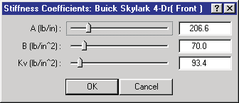 Figure 11-20: Vehicle Exterior Stiffness Coefficients dialogs allow the user to view and edit the A, B and Kv stiffness coefficients for the selected surface.
(updated: the A/B/Kv Stiffness Coefficients dialog is used when HVE is running in 2-D mode. In 3-D mode, the Stiffness button in the Vehicle Dimensions dialogs opens the Vehicle Exterior Stiffness dialog instead, which additionally supports 3-D — constant/linear/quadratic/cubic — stiffness definitions, saturation crush and maximum crush. The Stiffness button is disabled for Fixed Barrier and Movable Barrier vehicle types.)
To display or edit the current vehicle's A, B and Kv stiffness coefficients, perform the following steps:
- In the Vehicle Viewer, click on the front, right side, back or left side exterior sphere. The appropriate dialog (CG to Front, Right Side, Back, Left Side, Top or Bottom) will be displayed.
- Click on Stiffness. The Stiffness Coefficients dialog for the current surface will be displayed.
- View and/or edit the stiffness properties.
- Press OK to accept the changes.
The Exterior Stiffness parameters are described below.
- 'A' Stiffness Coefficient — Assigns the force per unit of damage width required to initiate permanent crush (see Figures 11-20 and 11-21).
- 'B' Stiffness Coefficient — Assigns the linear spring rate (force vs deflection constant) per unit of damage width required to produce permanent crush (see Figures 11-20 and 11-21).
- 'Kv' Stiffness Coefficient — Assigns the linear spring rate (force vs deflection constant) per unit of damage width required to produce permanent crush. This value differs from the B constant in that it assumes the force vs deflection graph goes through zero (i.e., A = 0).
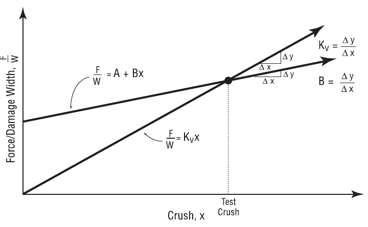 Figure 11-21: Force vs Deflection characteristics of a vehicle, and their relationship to the A, B and Kv stiffness coefficients (see also references 2.8–2.14, 4.20, 4.29).
Table 11-11: Vehicle Exterior Stiffness Coefficients Parameters
| Parameter | Unit Name | Description |
|---|---|---|
| A Stiffness | UtVehAStiff | Vehicle 'A' stiffness coefficient |
| B Stiffness | UtVehBStiff | Vehicle 'B' stiffness coefficient |
| Kv Stiffness | UtVehKStiff | Vehicle 'Kv' stiffness coefficient |
See also the code-verified reference pages: Stiffness Coefficients dialog (2-D), A Stiffness, B Stiffness.
Source: HVE User's Manual (Version 5, Seventh Edition, Jan 2006), Chapter 11, pages 11-36..11-39 — updated against source code (HVEINV-64, Physics) 2026-07-05.
← Previous: Chapter 11 — Vehicle Model Definition (Part A: Sprung Mass) | Index | Next: Chapter 11 — Vehicle Model Definition (Part C: Suspension) →